In this guide, we shall cover the PWM mode in the timer and fade an LED connected to 1 on the timer channel.
In this guide, we shall cover the following:
- What is PWM.
- Developing the driver.
- Connection.
- Results.
1. What is PWM:
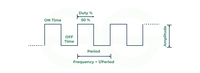
Pulse-width modulation (PWM), also known as pulse-duration modulation (PDM) or pulse-length modulation (PLM), is a technique used to represent a signal as a rectangular wave with a varying duty cycle (and sometimes a varying period). Let’s break it down:
- Duty Cycle: The duty cycle refers to the ratio of the time the signal is “on” (high) to the total time of one complete cycle. It is expressed as a percentage. For example, if a signal is on for 60% of the time and off for 40%, the duty cycle is 60%.
- Average Power Control: PWM is particularly useful for controlling the average power or amplitude delivered by an electrical signal. By switching the supply between 0% and 100% at a rate faster than the load can respond, we can effectively control the average power delivered to the load.
- Applications:
- Motor Control: PWM is commonly used to control motors (such as in fans, pumps, and robotics) because motors are not easily affected by discrete switching.
- Solar Panels: It’s a key method for controlling the output of solar panels to match battery requirements.
- Digital Controls: PWM works well with digital controls, allowing precise duty cycle adjustments.
- Communication Systems: In some cases, PWM duty cycles have been used to convey information over communication channels.
- Switching Frequency: The switching frequency (how often the signal switches on and off) varies depending on the application. It can range from several times a minute (e.g., electric stoves) to tens or hundreds of kilohertz (e.g., audio amplifiers).
- Advantages:
- Low power loss in switching devices (almost zero current when off).
- Works well with digital control systems.
- Used in various applications due to its flexibility.
- Disadvantages:
- Choosing the right switching frequency is crucial for smooth control.
- Too high a frequency can stress mechanical components.
- Too low a frequency can cause load oscillations.
In summary, PWM allows precise control of average power delivery by rapidly switching the signal on and off.
2. Developing the Driver:
Create new project with name of TIM_PWM.
open clock configuration tab as following:
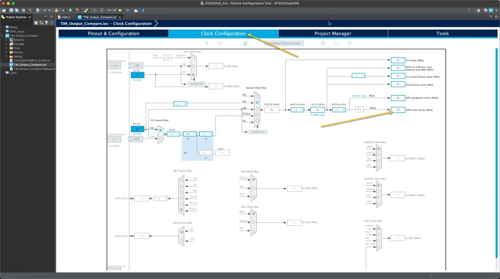
Notice the value of APB Timer clocks which is 16MHz in this case.
Now, from Pinout and Configuration tab, enable timer 3:
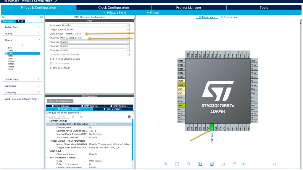
Set the clock source to be internal, Set channel 1 to be PWM Generation CH1 and you will notice CubeMX already set PA6 to work with timer3 in PWM.Now, we need to configure the timer.First we need to set the required prescaller and counter period.Since the timer clock is 16MHz and we need to get 10KHz, we shall use the following equation to determine the required frequency and period as following: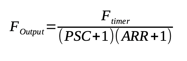
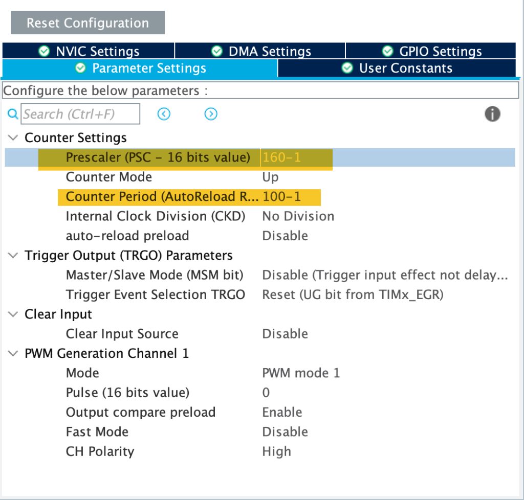
By setting the PSC to 160-1 and ARR to 100-1, we get the desired frequency of 10KHz.
Hence, configure the timer as following:
Save the project and this should generate the project.
In user code 2 in main function:
Enable timer 3 in PWM mode as following:
HAL_TIM_PWM_Start(&htim3, TIM_CHANNEL_1);
In user code 3, we shall vary the duty cycle as following:
	  for (int i=0;i<100;i++)
	  {
		  TIM3->CCR1=i;
		  HAL_Delay(10);
	  }
	  HAL_Delay(50);
	  for (int i=100;i>0;i--)
	  {
		  TIM3->CCR1=i;
		  HAL_Delay(10);
	  }
	  HAL_Delay(50);
By using the CCRx register of the timer, it allows us to change the duty cycle with ease.
The duty cycle can be calculate as following:

3. Connection:
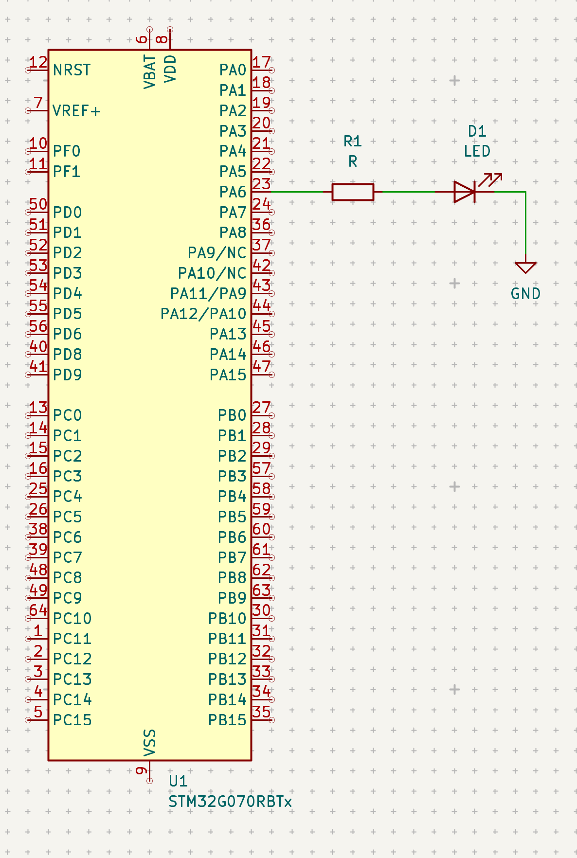
The connection as following and you will need those extra componets:
- Breadboard.
- Hockup wires.
- LED (any color).
- 100Ohm resistor.
The connection as following:
4. Results:
Happy coding 🙂
Add Comment