In the previous guide (here), we initialized the peripheral and filter to accept data with identifier of 0x446.
In this third part of CANBus guide, we shall start to transmit data from one STM32 and receive it from another STM32. (From STM32Ff407 to STM32F446).
- Developing the data structure.
- Developing the header file.
- Transmit function.
- Receive Function.
- Main transmit code.
- Main receive code.
- Results.
In this guide, we shall cover the following:
13. Developing the Data Structure:
We start with CANBus.h header file.
Within the header file, declare the following two structures:
The transmit data structure:
typedef struct CANBusTxFrame
{
	uint32_t identifier;
	uint8_t length;
	uint8_t data[8];


}CANBusTxFrameDef;
The structure has three elements as following:
- Identifier which hold the identifier number of the CAN node.
- Length which is the length of the data to transmitted (Maximum 8).
- data array of 8 elements which is the data buffer to hold the data to send.
The receiver data structure:
typedef struct CANBusRxFrame
{
	uint32_t identifier;
	uint8_t length;
	uint8_t data[8];


}CANBusRxFrameDef;
It is similar to transmit data structure.
Thats all for the data structure part.
14. Developing the Header File:
We shall continue with the header.
Declare the following functions:
/*
 * @brief This function will initialize the CANBus pins (PB8 and PB9) .
 * @return nothing.
 * */
void CANBus_Pins_Init(void);


/*
 * @brief This function will initialize the CANBus.
 * @return nothing.
 * @see source file for configuration parameters
 * */
void CANBus_Init(void);

/*
 * @brief This function will start the CANBus Peripheral.
 * @return nothing.
 * */
void CANBus_Start(void);


/*
 * @brief This function will configure the filter of CANBus.
 * @return nothing.
 * @see source file for filter parameters
 * */
void Filter_Configuration(void);


/*
 * @brief This function will transmit data over CANBus.
 * @param pointer to CANBusTxFrame data structure.
 * @return nothing.
 * */
void CANBus_SendMessage(CANBusTxFrameDef *TXFrame);


/*
 * @brief This function will receive data over CANBus.
 * @param pointer to CANBusRxFrame data structure.
 * @return nothing.
 * */
void CANBus_ReceiveMessage(CANBusRxFrameDef *RXFrame);
Hence, the entire header file as following:
/*
 * CANBus.h
 *
 *  Created on: Dec 29, 2023
 *      Author: hussamaldean
 */

#ifndef CANBUS_H_
#define CANBUS_H_

#include "stdint.h"


/*
 * @brief This data structure holds the CANBus
 * message to be send.
 * */

typedef struct CANBusTxFrame
{
	uint32_t identifier; /*@brief The identifier of the CANBus Message*/
	uint8_t length;      /*@brief The length of the CANBus Message*/
	uint8_t data[8];     /*@brief The buffer which hold the data to be sent*/


}CANBusTxFrameDef;


/*
 * @brief This data structure holds the CANBus
 * message to be received.
 * */

typedef struct CANBusRxFrame
{
	uint32_t identifier; /*@brief The identifier of the CANBus Message*/
	uint8_t length;      /*@brief The length of the CANBus Message*/
	uint8_t data[8];     /*@brief The buffer which hold the data to be received*/

}CANBusRxFrameDef;


/*
 * @brief This function will initialize the CANBus pins (PB8 and PB9) .
 * @return nothing.
 * */
void CANBus_Pins_Init(void);


/*
 * @brief This function will initialize the CANBus.
 * @return nothing.
 * @see source file for configuration parameters
 * */
void CANBus_Init(void);

/*
 * @brief This function will start the CANBus Peripheral.
 * @return nothing.
 * */
void CANBus_Start(void);


/*
 * @brief This function will configure the filter of CANBus.
 * @return nothing.
 * @see source file for filter parameters
 * */
void Filter_Configuration(void);


/*
 * @brief This function will transmit data over CANBus.
 * @param pointer to CANBusTxFrame data structure.
 * @return nothing.
 * */
void CANBus_SendMessage(CANBusTxFrameDef *TXFrame);


/*
 * @brief This function will receive data over CANBus.
 * @param pointer to CANBusRxFrame data structure.
 * @return nothing.
 * */
void CANBus_ReceiveMessage(CANBusRxFrameDef *RXFrame);


#endif /* CANBUS_H_ */
Thats all for the header file.
14. Transmit Function:
For transmit function:
void CANBus_SendMessage(CANBusTxFrameDef *TXFrame )
The function takes pointer to CANBusRxFrameDef data structure which holds the identifier, length and data.
Within this function:
First wait until the Mailbox is free by checking TME0 (Transmit Mailbox 0 is empty) if it is set to 1 or not:

    // Wait until the transmit mailbox is empty
    while ((CAN1->TSR & CAN_TSR_TME0) == 0);
Set identifier mode to be standard:

    // Set the standard identifier and data length
    CAN1->sTxMailBox[0].TIR &= ~CAN_TI0R_STID;
Set the identifier number:
    // Configure the transmit mailbox identifier
    CAN1->sTxMailBox[0].TIR |= (TXFrame->identifier << 21);
Set length of the data:

    // Configure data length
    CAN1->sTxMailBox[0].TDTR |= (TXFrame->length << 0);
Store the buffer into the CANBus FIFO:

    CAN1->sTxMailBox[0].TDLR=
    		((uint32_t)TXFrame->data[3] << CAN_TDL0R_DATA3_Pos) |
            ((uint32_t)TXFrame->data[2] << CAN_TDL0R_DATA2_Pos) |
            ((uint32_t)TXFrame->data[1] << CAN_TDL0R_DATA1_Pos) |
            ((uint32_t)TXFrame->data[0] << CAN_TDL0R_DATA0_Pos);

    CAN1->sTxMailBox[0].TDHR=
            ((uint32_t)TXFrame->data[7] << CAN_TDH0R_DATA7_Pos) |
            ((uint32_t)TXFrame->data[6] << CAN_TDH0R_DATA6_Pos) |
            ((uint32_t)TXFrame->data[5] << CAN_TDH0R_DATA5_Pos) |
            ((uint32_t)TXFrame->data[4] << CAN_TDH0R_DATA4_Pos);
Start the transmission :

    // Set the TXRQ bit to request transmission
    CAN1->sTxMailBox[0].TIR |= CAN_TI0R_TXRQ;
Thats all for the transmission part.
15.Receive Function:
We start with the send message function:
void CANBus_ReceiveMessage(CANBusRxFrameDef *RXFrame)
The function will take pointer to CANBusRxFrame data struct.
Within the function:
Check if the FIFO 0 has pending message:

if (CAN1->RF0R & CAN_RF0R_FMP0) {Within the if condition:
Get the identifier number:

        // Read the received identifier
        RXFrame->identifier = (CAN1->sFIFOMailBox[0].RIR >> 3) & 0x1FFFFFFF;
Get the length of the data:

        // Read the data length
        RXFrame->length = CAN1->sFIFOMailBox[0].RDTR & 0x0F;
Clear the old data:
        /*Clear old data*/
        for (int i=0;i<8;i++)
        {
        	RXFrame->data[i]=0;
        }
Store the new values:
        RXFrame->data[0]=CAN1->sFIFOMailBox[0].RDLR >>CAN_RDL0R_DATA0_Pos;
        RXFrame->data[1]=CAN1->sFIFOMailBox[0].RDLR >>CAN_RDL0R_DATA1_Pos;
        RXFrame->data[2]=CAN1->sFIFOMailBox[0].RDLR >>CAN_RDL0R_DATA2_Pos;
        RXFrame->data[3]=CAN1->sFIFOMailBox[0].RDLR >>CAN_RDL0R_DATA3_Pos;

        RXFrame->data[4]=CAN1->sFIFOMailBox[0].RDHR >>CAN_RDH0R_DATA4_Pos;
        RXFrame->data[5]=CAN1->sFIFOMailBox[0].RDHR >>CAN_RDH0R_DATA5_Pos;
        RXFrame->data[6]=CAN1->sFIFOMailBox[0].RDHR >>CAN_RDH0R_DATA6_Pos;
        RXFrame->data[7]=CAN1->sFIFOMailBox[0].RDHR >>CAN_RDH0R_DATA7_Pos;
Release the FIFO0:
        // Release the FIFO (not necessary for FIFO0)
        CAN1->RF0R |= CAN_RF0R_RFOM0;
Finally toggle the LED connected to PA5:
GPIOA->ODR^=GPIO_ODR_OD5;
Hence, the entire source code as following:
#include "CANBus.h"
#include "stm32f4xx.h"

#define CAN_AF 0x09

void CANBus_Pins_Init(void)
{
	/*Enable clock access to GPIOB*/
	RCC->AHB1ENR|=RCC_AHB1ENR_GPIOBEN;

	/*Set PB8 and PB9 to alternate function*/
	GPIOB->MODER|=GPIO_MODER_MODE8_1|GPIO_MODER_MODE9_1;
	GPIOB->MODER&=~(GPIO_MODER_MODE8_0|GPIO_MODER_MODE9_0);

	/*Select which alternate function*/
	GPIOB->AFR[1]|=(CAN_AF<<GPIO_AFRH_AFSEL8_Pos)|(CAN_AF<<GPIO_AFRH_AFSEL9_Pos);

}

void CANBus_Init(void)
{


	/*Enable Clock access to CAN1*/
	RCC->APB1ENR|=RCC_APB1ENR_CAN1EN;


    /* Enter Initialization mode*/
    CAN1->MCR |= CAN_MCR_INRQ;
    /*Wait until CANBus peripheral is in initialization mdoe*/
    while ((CAN1->MSR & CAN_MSR_INAK)==0U);

    // Enable CAN1 peripheral
    CAN1->MCR &= ~CAN_MCR_SLEEP;
    while ((CAN1->MSR & CAN_MSR_SLAK)!=0U);


    /*Configure the timing with the following parameters
     * Normal mode.
     * Loop back mode is disabled.
     * Resynchronization jump width to 1 (value - 1).
     * Prescale of 10. (value - 1)
     * Time quanta segment 1 is 2 (value - 1)
     * Time quanta segment 2 is 1 (value - 1)
     * Baud is 400Kbps
     * */

    /*Reset the non-zero initial values*/
    CAN1->BTR&=~(CAN_BTR_TS1_Msk|CAN_BTR_TS2_Msk|CAN_BTR_SJW_Msk);

    CAN1->BTR=(1<<CAN_BTR_TS1_Pos)|(0<<CAN_BTR_TS2_Pos)
    		|(9U<<CAN_BTR_BRP_Pos);

    /*Other basic parameters can be configured according your application
     * The following is the configuration:
     * Time triggered communication is disabled.
     * Automatic bus-off management is disabled.
     * Automatic wake-up is disabled.
     * Automatic retransmission is off.
     * Receive FIFO lock mode is disabled.
     * Transmit FIFO Priority is off
     * */
}


void Filter_Configuration(void)
{

	/*Filter is filter 18 and it will accept data from identifier 0x446*/

	/* Set the filter initialization mode*/
	CAN1->FMR |= CAN_FMR_FINIT;

	/*Set the slave Filter to start from 20*/
	CAN1->FMR &=~(CAN_FMR_CAN2SB_Msk);
	CAN1->FMR |=(20<<CAN_FMR_CAN2SB_Pos);

	/*Disable Filter 18*/
	CAN1->FA1R&=~(CAN_FA1R_FACT18);

	/* Set to 1 for 32-bit scale configuration*/
    CAN1->FS1R |= CAN_FS1R_FSC18;


    CAN1->FM1R &= ~CAN_FM1R_FBM18; // Set to 0 for identifier mask mode

    CAN1->sFilterRegister[18].FR1 = (0x446<<5) << 16; // Identifier

    CAN1->sFilterRegister[18].FR2 = (0x446<<5) << 16; // Identifier mask

    /*Assign filter 18 to FIFO0*/
    CAN1->FFA1R&=~CAN_FFA1R_FFA18;

    // Activate filter 18
    CAN1->FA1R |= CAN_FA1R_FACT18;


    CAN1->FMR &= ~CAN_FMR_FINIT; // Clear the filter initialization mode


}

void CANBus_Start(void)
{
    // Leave Initialization mode
    CAN1->MCR &= ~CAN_MCR_INRQ;
    while (CAN1->MSR & CAN_MSR_INAK);

}


void CANBus_SendMessage(CANBusTxFrameDef *TXFrame )
{
    // Wait until the transmit mailbox is empty
    while ((CAN1->TSR & CAN_TSR_TME0) == 0);

    // Set the standard identifier and data length
    CAN1->sTxMailBox[0].TIR &= ~CAN_TI0R_STID;

    // Configure the transmit mailbox identifier
    CAN1->sTxMailBox[0].TIR |= (TXFrame->identifier << 21);

    // Configure data length
    CAN1->sTxMailBox[0].TDTR |= (TXFrame->length << 0);


    CAN1->sTxMailBox[0].TDLR=
    		((uint32_t)TXFrame->data[3] << CAN_TDL0R_DATA3_Pos) |
            ((uint32_t)TXFrame->data[2] << CAN_TDL0R_DATA2_Pos) |
            ((uint32_t)TXFrame->data[1] << CAN_TDL0R_DATA1_Pos) |
            ((uint32_t)TXFrame->data[0] << CAN_TDL0R_DATA0_Pos);

    CAN1->sTxMailBox[0].TDHR=
            ((uint32_t)TXFrame->data[7] << CAN_TDH0R_DATA7_Pos) |
            ((uint32_t)TXFrame->data[6] << CAN_TDH0R_DATA6_Pos) |
            ((uint32_t)TXFrame->data[5] << CAN_TDH0R_DATA5_Pos) |
            ((uint32_t)TXFrame->data[4] << CAN_TDH0R_DATA4_Pos);

    // Set the TXRQ bit to request transmission
    CAN1->sTxMailBox[0].TIR |= CAN_TI0R_TXRQ;
}

void CANBus_ReceiveMessage(CANBusRxFrameDef *RXFrame)
{
    if (CAN1->RF0R & CAN_RF0R_FMP0) { // Check if there's a pending message in FIFO0
        // Read the received identifier
        RXFrame->identifier = (CAN1->sFIFOMailBox[0].RIR >> 3) & 0x1FFFFFFF;

        // Read the data length
        RXFrame->length = CAN1->sFIFOMailBox[0].RDTR & 0x0F;

        /*Clear old data*/
        for (int i=0;i<8;i++)
        {
        	RXFrame->data[i]=0;
        }


        RXFrame->data[0]=CAN1->sFIFOMailBox[0].RDLR >>CAN_RDL0R_DATA0_Pos;
        RXFrame->data[1]=CAN1->sFIFOMailBox[0].RDLR >>CAN_RDL0R_DATA1_Pos;
        RXFrame->data[2]=CAN1->sFIFOMailBox[0].RDLR >>CAN_RDL0R_DATA2_Pos;
        RXFrame->data[3]=CAN1->sFIFOMailBox[0].RDLR >>CAN_RDL0R_DATA3_Pos;

        RXFrame->data[4]=CAN1->sFIFOMailBox[0].RDHR >>CAN_RDH0R_DATA4_Pos;
        RXFrame->data[5]=CAN1->sFIFOMailBox[0].RDHR >>CAN_RDH0R_DATA5_Pos;
        RXFrame->data[6]=CAN1->sFIFOMailBox[0].RDHR >>CAN_RDH0R_DATA6_Pos;
        RXFrame->data[7]=CAN1->sFIFOMailBox[0].RDHR >>CAN_RDH0R_DATA7_Pos;


        // Release the FIFO (not necessary for FIFO0)
        CAN1->RF0R |= CAN_RF0R_RFOM0;

        GPIOA->ODR^=GPIO_ODR_OD5;
    }
}
Thats all for the CANBus.
16. Main Transmit Code:
The code of the transmit device (STM32F407 in this case):
#include "delay.h"
#include "CANBus.h"
#include "stdlib.h"

CANBusTxFrameDef TXFrame;

int main(void)
{

	delay_init(16000000);
	CANBus_Pins_Init();
	CANBus_Init();
	Filter_Configuration();
	CANBus_Start();
	srand(millis());
	while(1)
	{
		for (int i=0;i<8;i++)
		{
			TXFrame.data[i]=random()%255;
		}

		TXFrame.identifier=0x446;
		TXFrame.length=8;
		CANBus_SendMessage( &TXFrame );
		delay(1000);

	}


}
We shall randomize the transmitted data every second.
17. Main Receiver Code:
The receiver which is STM32F446RE Nucleo-64:
#include "delay.h"
#include "CANBus.h"
#include "stm32f4xx.h"
CANBusRxFrameDef RXFrame;


int main(void)
{

	RCC->AHB1ENR|=RCC_AHB1ENR_GPIOAEN;
	GPIOA->MODER|=GPIO_MODER_MODE5_0;
	GPIOA->MODER&=~GPIO_MODER_MODE5_1;
	delay_init(16000000);
	CANBus_Pins_Init();
	CANBus_Init();
	Filter_Configuration();
	CANBus_Start();


	while(1)
	{
		CANBus_ReceiveMessage(&RXFrame);


	}


}
18. Results:
Open new debug session and put RXFrame in Live Expression and you should get the following:
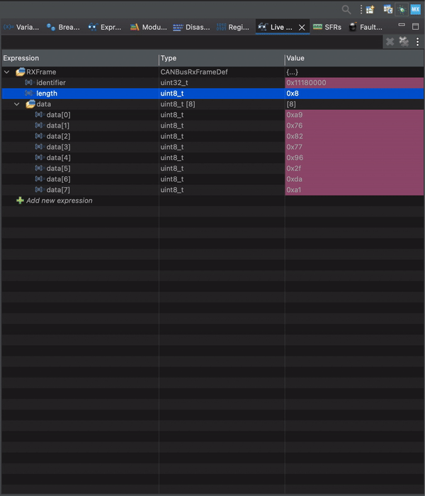
You will also notice the LED will toggle at rate of 1 second.
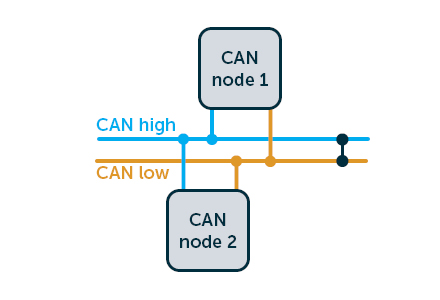
Note: If there is not data to be transmitted, make sure that you terminated the CANH and CANL properly and use twisted pair of wires.
Happy coding 😉
4 Comments
Dear Husamuldeen,
Thank you for sharing your insightful blog post. I found it particularly engaging. I attempted to implement the provided code with two Nucleo STM32F446re boards. However, I encountered an issue during testing.
While the connection and communication function properly, I observed that communication is successful only from one side, specifically from node 1 to node 2. However, upon switching the roles of the transmitter and receiver, from node 2 to node 1, I noticed discrepancies in the received values, receiving incorrect data instead of the expected values.
Furthermore, on the receiving end, the data length is reported as 10 instead of the expected 8 bytes.
Do you think that is because i am using 2 nucleo stm32f446? or it could be a problem inside the nucleo borad itself?
thank you in advance for your support 🙂
best regards.
Mohamed
Hi,
make sure you configured the filter correctly, use twisted pair and terminate both end with 120Ohm and same baudrate.
Hello Husamuldeen,
Thank you for your response. I have everything the same on both boards: I use twisted pair and 120 ohms on both sides. The thing that will drive me crazy is that it only works from one side. If I switch the roles of the boards (TX – RX), it stops working. Instead of receiving 8 bytes, I get 113 bytes plus error messages. Instead of receiving 1, 2, 3, 4, 5, 6, 7, 8, I receive 85, -52, 0, 25, 36, 47, -2, 5
I am not sure what is the issue.
Will have to investigate if there is an issue within the code.
Meanwhile, try to check the hardware if everything is ok.
Add Comment