In this guide, we shall emulate the parallel output that had been used before to communicate with printers which eventually replaced with serial port and USB. This guide focuses on the output which will be useful in upcoming guide.
In this guide, we shall cover the following:
- What is Parallel Port.
- Developing the parallel output driver.
- LEDs connection
- Results.
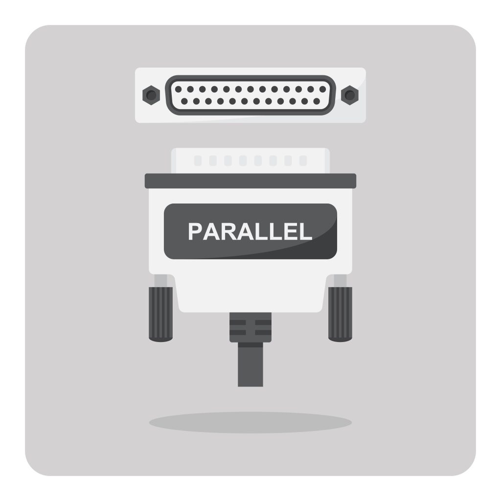
1. What is Parallel Port:
In computing, a parallel port is a type of interface found on early computers (personal and otherwise) for connecting peripherals. The name refers to the way the data is sent; parallel ports send multiple bits of data at once (parallel communication), as opposed to serial communication, in which bits are sent one at a time. To do this, parallel ports require multiple data lines in their cables and port connectors and tend to be larger than contemporary serial ports, which only require one data line. (From Wikipedia here).
2. Developing the Parallel Output Driver:
Before heading into developing the driver, take a look at this guide to have understand how to configure the timer to work with DMA and toggle a GPIO pin.
We start off by declaring the following macro:
#define data_size 5
This macro will indicate the size of the array.
Declare the array which holds the data to be sent:
uint32_t gpio_pattern[data_size];
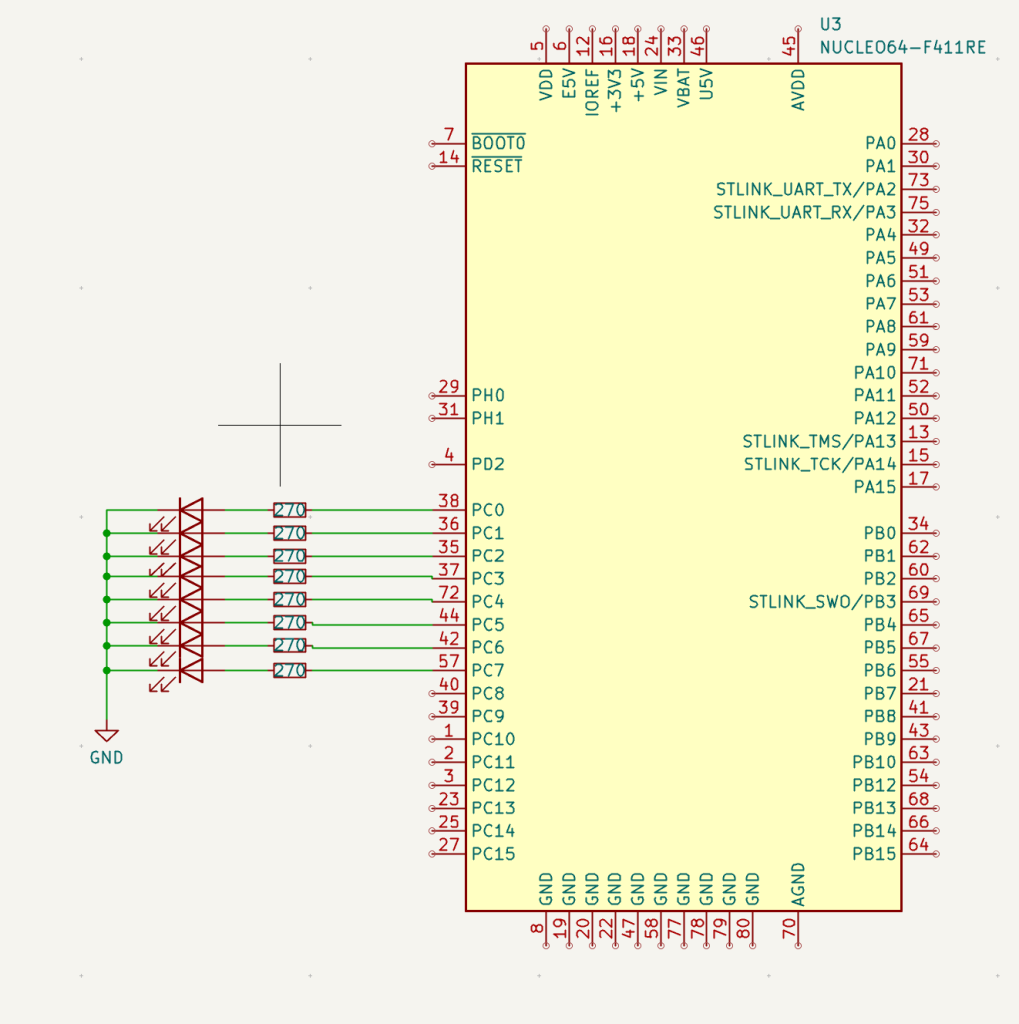
Since we are dealing with parallel port, we shall use Pin0 to Pin7 of PortC of STM32F411 Nucleo-64.
In main function:
Enable clock access to GPIOC:
	/*Enable clock access to GPIOA*/
	RCC->AHB1ENR|=RCC_AHB1ENR_GPIOCEN;
Set Pin0 to Pin7 as output:
	/*Set PC0 to PC7 as output*/
	GPIOC->MODER|=GPIO_MODER_MODE0_0|GPIO_MODER_MODE1_0|GPIO_MODER_MODE2_0
			|GPIO_MODER_MODE3_0|GPIO_MODER_MODE4_0|GPIO_MODER_MODE5_0|
			GPIO_MODER_MODE6_0|GPIO_MODER_MODE7_0;

	GPIOC->MODER&=~(GPIO_MODER_MODE0_1|GPIO_MODER_MODE1_1|GPIO_MODER_MODE2_1
			|GPIO_MODER_MODE3_1|GPIO_MODER_MODE4_1|GPIO_MODER_MODE5_1
			|GPIO_MODER_MODE6_1|GPIO_MODER_MODE7_1);
For timer configuration:
- Enable DMA request when update (overflow) occurs.
- Set the prescaller to 16000-1.
- Set the ARR to 100 to achieve toggle rate of 10Hz.
	/*Timer configuration*/

	RCC->APB2ENR  |=  RCC_APB2ENR_TIM1EN;

	TIM1->DIER=TIM_DIER_UDE;

	TIM1->PSC=16000-1; /*16 000 000 / 16 000 =1 000*/
	TIM1->ARR=100-1; /*1 000 / 1 000 = 1HZ*/
DMA configuration as following:
Configure the DMA with the following parameters:
- Channel 6.
- Memory and Peripheral size to be word size (32-bit).
- Memory increment mode.
- Circular mode.
- Direction: Memory to peripheral.
	/*DMA configuration*/


	RCC->AHB1ENR|=RCC_AHB1ENR_DMA2EN;

	DMA2_Stream5->CR&=DMA_SxCR_EN;

	while((DMA2_Stream5->CR)&DMA_SxCR_EN){;}

	DMA2_Stream5->CR|=(CH6<<DMA_SxCR_CHSEL_Pos)|DMA_SxCR_MSIZE|DMA_SxCR_PSIZE|
			DMA_SxCR_MINC|DMA_SxCR_CIRC|DMA_SxCR_DIR_0;

	DMA2_Stream5->NDTR=(uint32_t)data_size;

	DMA2_Stream5->PAR=(uint32_t)(&GPIOC->ODR);

	DMA2_Stream5->M0AR=(uint32_t)(gpio_pattern);
Enable the DMA channel:
	/*Launch DMA*/
	DMA2_Stream5->CR|=DMA_SxCR_EN;
Launch the timer:
	/*Launch Timer*/
	TIM1->CR1     |= TIM_CR1_CEN;
In while 1 loop:
- Wait a little by wasting CPU cycles.
- Randomise the values in the array.
		for (int j=0;j<100000;j++);
		/*Fill the array with random data*/
		for (int i=0; i<data_size;i++)
		{
			gpio_pattern[i]=random()%256;
		}
This will provide randomness to be observed.
Hence, the entire code as following:
#include "stm32f4xx.h"
#include "stdint.h"

#include "stdlib.h"

#define data_size 	5
#define CH6 		0x06

uint32_t gpio_pattern[data_size];


int main(void)
{
	/*GPIO Configuration*/

	/*Enable clock access to GPIOA*/
	RCC->AHB1ENR|=RCC_AHB1ENR_GPIOCEN;

	/*Set PC0 to PC7 as output*/
	GPIOC->MODER|=GPIO_MODER_MODE0_0|GPIO_MODER_MODE1_0|GPIO_MODER_MODE2_0
			|GPIO_MODER_MODE3_0|GPIO_MODER_MODE4_0|GPIO_MODER_MODE5_0|
			GPIO_MODER_MODE6_0|GPIO_MODER_MODE7_0;

	GPIOC->MODER&=~(GPIO_MODER_MODE0_1|GPIO_MODER_MODE1_1|GPIO_MODER_MODE2_1
			|GPIO_MODER_MODE3_1|GPIO_MODER_MODE4_1|GPIO_MODER_MODE5_1
			|GPIO_MODER_MODE6_1|GPIO_MODER_MODE7_1);


	/*Timer configuration*/

	RCC->APB2ENR  |=  RCC_APB2ENR_TIM1EN;

	TIM1->DIER=TIM_DIER_UDE;

	TIM1->PSC=16000-1; /*16 000 000 / 16 000 =1 000*/
	TIM1->ARR=100-1; /*1 000 / 1 000 = 1HZ*/


	/*DMA configuration*/


	RCC->AHB1ENR|=RCC_AHB1ENR_DMA2EN;

	DMA2_Stream5->CR&=DMA_SxCR_EN;

	while((DMA2_Stream5->CR)&DMA_SxCR_EN){;}

	DMA2_Stream5->CR|=(CH6<<DMA_SxCR_CHSEL_Pos)|DMA_SxCR_MSIZE|DMA_SxCR_PSIZE|
			DMA_SxCR_MINC|DMA_SxCR_CIRC|DMA_SxCR_DIR_0;

	DMA2_Stream5->NDTR=(uint32_t)data_size;

	DMA2_Stream5->PAR=(uint32_t)(&GPIOC->ODR);

	DMA2_Stream5->M0AR=(uint32_t)(gpio_pattern);


	/*Launch DMA*/
	DMA2_Stream5->CR|=DMA_SxCR_EN;

	/*Launch Timer*/
	TIM1->CR1     |= TIM_CR1_CEN;

	while(1)
	{
		for (int j=0;j<100000;j++);
		/*Fill the array with random data*/
		for (int i=0; i<data_size;i++)
		{
			gpio_pattern[i]=random()%256;
		}
	}

}
3. LEDs connection:
This guide requires the following extra components:
- Breadboard.
- 8LEDs.
- 8 270Ohm resistors.
- Hookup wires.
Connect the LEDs as following:
4. Results:
Happy coding 🙂
Add Comment