
In this third section of the thirteenth part of board support package, we shall use the BSP of DMA to transfer data from the memory to peripheral which is SPI in this case.
In this guide, we shall cover the following:
- Enabling DMA for SPI.
- Configure the DMA.
- Code.
- Results.
1. Enabling DMA for SPI:
Open spi_bsp.h header file and declare this enum:
typedef enum
{
	SPI_DMA_Disabled=0,
	SPI_DMA_Enable=1

}SPI_DMATypedef;
This defines the DMA enabling process in the source code.
Within SPI_ConfigTypedef include the following variable:
uint8_t DMA_Enable;
This will either enable or disable the DMA.
Hence, the updated data structure as following:
typedef struct
{
	uint8_t mode;
	uint8_t dataFromat;
	uint8_t slaveManagement;
	uint8_t LSBFirst;
	uint8_t baud;
	uint8_t CPOL;
	uint8_t CPHA;
	uint8_t DMA_Enable;
}SPI_ConfigTypedef;
Now, open spi_bsp.c source file.
Within BSP_SPI_Config function, before starting the SPI: include the following line:
	if (con->DMA_Enable==SPI_DMA_Enable)
	{
		spi->CR2|=SPI_CR2_TXDMAEN|SPI_CR2_RXDMAEN;
	}
This will enable DMA for both, TX and RX part of SPI.
Hence, the updated BSP_SPI_Config as following:
void BSP_SPI_Config(SPI_TypeDef *spi, SPI_ConfigTypedef *con)
{

	switch (con->mode)
	{

		 case Master_mode:  spi->CR1|=(1<<SPI_CR1_MSTR_Pos);
		 	 break;
		 case Slave_mode:   spi->CR1&=~(1<<SPI_CR1_MSTR_Pos); break;
		 default : break;
	}

	switch (con->dataFromat)
	{
		case MSB_First: spi->CR1&=~(con->dataFromat<<SPI_CR1_LSBFIRST_Pos);
			break;
		case LSB_First: spi->CR1|=(con->dataFromat<<SPI_CR1_LSBFIRST_Pos); break;
		default: break;
	}

	if(con->baud ==FCLK_2)
	{
		spi->CR1&=~(SPI_CR1_BR_Msk<<SPI_CR1_BR_Pos);
	}

	else
	{
		spi->CR1|=(con->baud<<SPI_CR1_BR_Pos);
	}


	if (con->CPOL==CPOL0)
	{
		spi->CR1&=~(1<<SPI_CR1_CPOL_Pos);
	}
	else
	{
		spi->CR1|=(con->CPOL<<SPI_CR1_CPOL_Pos);
	}

	if (con->CPHA==CPHA0)
	{
		spi->CR1&=~(1<<SPI_CR1_CPHA_Pos);
	}
	else
	{
		spi->CR1|=(con->CPHA<<SPI_CR1_CPHA_Pos);
	}


	switch (con->slaveManagement)
	{
	 case software_slave: spi->CR1|=(1<<SPI_CR1_SSM_Pos)|(1<<SPI_CR1_SSI_Pos); break;
	 case hardware_slave: spi->CR1&=~((1<<SPI_CR1_SSM_Pos)|(1<<SPI_CR1_SSI_Pos)); break;
	 default: break;
	}

	if (con->DMA_Enable==SPI_DMA_Enable)
	{
		spi->CR2|=SPI_CR2_TXDMAEN|SPI_CR2_RXDMAEN;
	}

	spi->CR1|=SPI_CR1_SPE;

}
Thats all for enabling DMA for SPI.
2. Configuring the DMA:
In main.c:
Declare a volatile to indicate that DMA finished transferring data and an array of 5 byte which holds the variable to be sent:
volatile uint8_t finished=0;


uint8_t SPI_TX[5]={0x00,0x22,0xFF,0x55,0x33};
Declare DMA configuration:
DMA_ConfigTypedef SPI_TX_DMA;
Declare CS pin:
GPIO_Output_Typedef CS_Pin;
GPIO configuration for SPI and CS pins:
GPIO_Configure_Typedef PA5_SPI,PA6_SPI,PA7_SPI;

	GPIOA_CLOCK_ENABLE();

	PA5_SPI.PinNumber=5;
	PA5_SPI.Mode=Alternate_function;
	PA5_SPI.AlternateType=AF5;
	PA5_SPI.OutPutspeed=High_Speed;


	PA6_SPI.PinNumber=6;
	PA6_SPI.Mode=Alternate_function;
	PA6_SPI.AlternateType=AF5;
	PA6_SPI.OutPutspeed=High_Speed;

	PA7_SPI.PinNumber=7;
	PA7_SPI.Mode=Alternate_function;
	PA7_SPI.AlternateType=AF5;
	PA6_SPI.OutPutspeed=High_Speed;

	GPIO_Initialization(GPIOA,&PA5_SPI);
	GPIO_Initialization(GPIOA,&PA6_SPI);
	GPIO_Initialization(GPIOA,&PA7_SPI);


	GPIO_Configure_Typedef CS_Pin_Config;

	CS_Pin_Config.PinNumber=pin0;
	CS_Pin_Config.Mode=OUTPUT;
	CS_Pin_Config.OutPutspeed=High_Speed;

	GPIO_Initialization(GPIOA,&CS_Pin_Config);

	GPIO_WritePin(GPIOA,&CS_Pin,Set);
SPI configuration:
	SPI_Enable_Clock(spi1);

	SPI_ConfigTypedef cSPI1;

	cSPI1.mode=Master_mode;
	cSPI1.slaveManagement=software_slave;
	cSPI1.baud=FCLK_32;
	cSPI1.CPHA=CPHA0;
	cSPI1.CPOL=CPOL0;
	cSPI1.LSBFirst=MSB_First;
	cSPI1.DMA_Enable=SPI_DMA_Enable;


	BSP_SPI_Config(SPI1,&cSPI1);
Similar to BSP for SPI with addition of DMA parameter only.
Since the required DMA is DMA2 Stream2 Channel2:
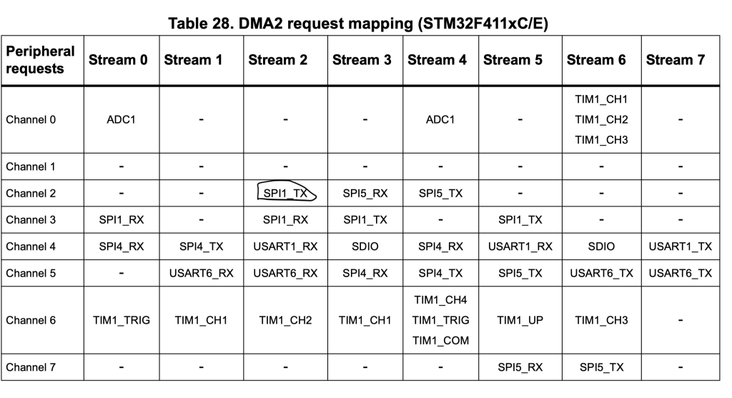
The configuration as following:
- Channel is 2.
- Single Mode (Non circular).
- Memory and Peripheral size is byte.
- Memory increment mode.
- Fixed peripheral address.
- Transfer complete interrupt.
	__BSP_DMA2__CLOCK_ENABLE();

	SPI_TX_DMA.DMA_Channel=Channel2;
	SPI_TX_DMA.CircularMode=SingleTransfer;
	SPI_TX_DMA.MemorySize=byte;
	SPI_TX_DMA.PerpheralSize=byte;
	SPI_TX_DMA.MemoryIncMode=incMode;
	SPI_TX_DMA.PeripheralIncMode=SingleTransfer;
	SPI_TX_DMA.Direction=memory2Peripheral;
	SPI_TX_DMA.InterruptEnable=InterruptEnbaled;
	SPI_TX_DMA.TransferCompleteInterrupt=TransferComplet;
	SPI_TX_DMA.DMAStream=dma2stream2;
	BSP_DMA_Init(DMA2_Stream2, &SPI_TX_DMA);
For the interrupt handler:
void DMA2_Stream2_handler(void)
{
	if((DMA2->LISR & DMA_LISR_TCIF2)==DMA_LISR_TCIF2)
	{
		finished=1;
	}

}
In while loop:
GPIO_WritePin(GPIOA,&CS_Pin,Reset);

		BSP_DMA_Transfer_Single_Buffer(DMA2_Stream2, &SPI1->DR,(uint32_t)&SPI_TX,5);

		while(finished ==0){;}

		finished=0;

		GPIO_WritePin(GPIOA,&CS_Pin,Set);

		BSP_Delay(200);
3.Code:
You may download the source code from here:
4. Results:
Using logic analyzer, connect the channels to PA5 and PA7 and you should get the following which is the array declared in the code:
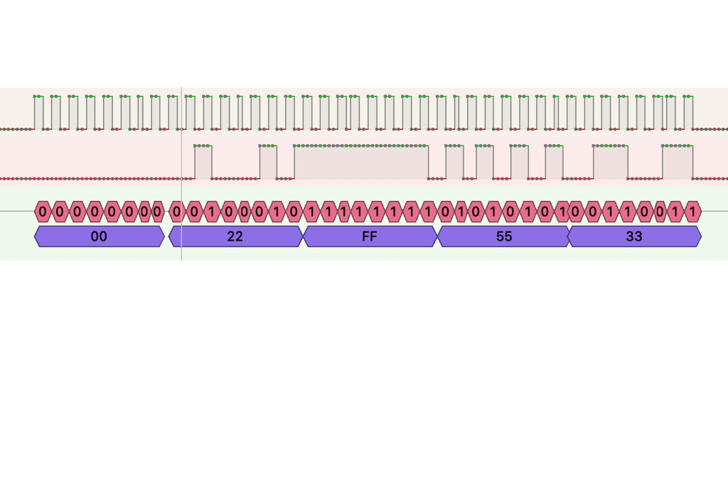
Happy coding 🙂
7 Comments
Dear Sir,
Good Morning, Please let me know Which Logic Analyzer (Brand) you are using to Display this screen.. thanks with regards, HSR-Rao
Hi,
this one:
https://www.amazon.com/HiLetgo-Analyzer-Ferrite-Channel-Arduino/dp/B077LSG5P2
Dear Sir,
Good Morning,Needed your help,
Downloaded the project, successfully, connected Logical-Analyzer,
Observed, that in ..
SPI_TX[5]={0x00,0x22,0xFF,0x55,0x33}, last two items are trimmed,
Tested again by repalcing it with…
SPI_TX[10]={0x00,0x11,0x22,0x33,0x44,0x55,0x66,0x77,0x88,0x99};
it is consistent…
Any thing mistake in my observation.. Please let me know, your comments.
thanks with regards,
HSR-Rao.
Hi,
remove CS line from the logic analyzer and see if you are able to see all data.
If yes, then everything is working correctly.
In order to send the data over SPI, after DMA finished transfer, use the busy flag of SR register in SPI to determine if all data have been transmitted or not.
Dear Sir,
Thanks for the suggesion provided,
I disconnected the Arduino-A0-Pin, which is same as PA0,
none of the data getting transmitted, so
Tried Tracing through the program-flow & data-flow in func.
void BSP_DMA_Transfer_Single_Buffer(…) {
dma->M0AR=dest;
dma->PAR=src;
dma->NDTR=len; CR |=DMA_SxCR_EN; }
whether the Variable Len(n), getting changed to (n-2) by any corruptions,
or by malfunctioning in my settings, found all are in sync.
Will Keep you updated on progress.
thanks with regards,
HSR-Rao.
In logic analyzer, don’t use CS.
Dear Sir,
Great, Thanks A Lot, It Worked, wrt your 8 exs on MPU9250,
4 are wrt BSPs(13-4,13-2,12,11), 4 are with STM32Lo53,
I had set all 4 Pins of SPI1s(PA5,PA6,PA7,PA0), so that it
is reusable for all. It worked fine with all, except 13-3,
Now after your suggestion, I changed in LogicAnalyzer, CS to NONE,
it Worked. Great .
But Now I need to Deeply understand How LA interprets…,
with warm regards,
HSR-Rao.
Add Comment