
In the previous guide (here), we took a look how to transmit data over SPI bus using DMA. In this guide, we shall use DMA with SPI in full duplex to transmit and receive at the same time. This will free the CPU to do something else (not covered in this guide).
In this guide, we shall cover the following:
- Enable DMA RX for SPI.
- DMA configuration.
- Receive data over DMA
- MPU9250 Connection.
- Code modification.
- Code.
- Results.
1. Enable DMA RX for SPI:
Open spi.h header and declare the following two enums:
typedef enum
{
	Tx_Done=1,
	TX_Inprogress=0

}SPI_TXStatus;

typedef enum
{
	Rx_Done=1,
	RX_Inprogress=0

}SPI_RXStatus;
Include these two new function:
void reset_finished();
uint8_t finished_receive();
void SPI_DMA_Receive(uint8_t *data,uint32_t size);
Hence, the entire header file as following:
#ifndef SPI_H_
#define SPI_H_

#include "stdint.h"


void spi_DMA_Init(void);
void SPI_DMA_Transmit(uint8_t *data,uint32_t size);
uint8_t finished_transfer();
void reset_finished();
uint8_t finished_receive();
void SPI_DMA_Receive(uint8_t *data,uint32_t size);
void spi_transmit(uint8_t *data,uint32_t size);


void cs_low();
void cs_high();


typedef enum
{
	Tx_Done=1,
	TX_Inprogress=0

}SPI_TXStatus;

typedef enum
{
	Rx_Done=1,
	RX_Inprogress=0

}SPI_RXStatus;


#endif /* SPI_H_ */
In order to configure SPI to receive data using DMA, we need to enable RXDMA bit in CR2 register:
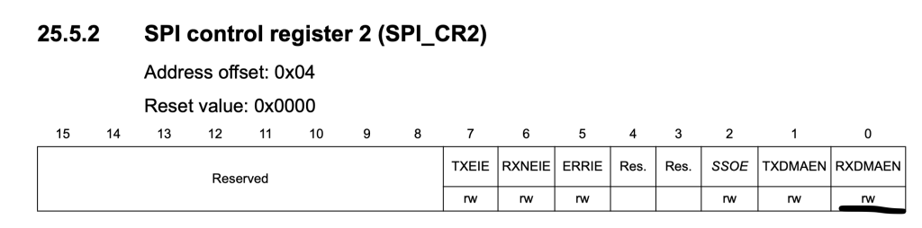
	/*Set RXDMA bit in CR2*/
	SPI1->CR2|=SPI_CR2_RXDMAEN;
Thats all for SPI section.
2. DMA Configuration:
Before we configure the DMA, we need to which channel is responsible for SPI1 RX:
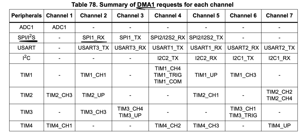
From DMA1 request map, we can see that DMA1 Channel2 is responsible for SPI RX:
The DMA configuration as following:
- Memory Increment mode.
- Read from peripheral.
- Transfer complete interrupt.
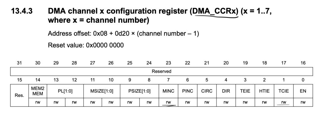
DMA1_Channel2->CCR|=DMA_CCR_MINC|DMA_CCR_TCIE;
Set peripheral to be SPI1->DR:
	/*Set Peripheral Address to be SPI1->DR*/
	DMA1_Channel2->CPAR=(uint32_t)& SPI1->DR;
Enable Interrupt of DMA1_Channel2 in NVIC:
	/*Enable DMA1_Channel3 interrupt in NVIC*/

	NVIC_EnableIRQ(DMA1_Channel2_IRQn);
Since we are using interrupt, we need to declare a variable to indicate that receiving data is finished:
volatile uint8_t SPI_Transfer_RX_Finished=0;
We shall also check if all data has been received:
uint8_t finished_receive()
{
	return SPI_Transfer_RX_Finished;
}
Clear flags:
void reset_finished()
{
	SPI_Transfer_TX_Finished=0;
	SPI_Transfer_RX_Finished=0;
}
Interrupt handler for DAM1_Channel2:
void DMA1_Channel2_IRQHandler (void)
{
	/*Check if the source is transfer complete*/

	if((DMA1->ISR & DMA_ISR_TCIF2) == DMA_ISR_TCIF2)
	{
		/*Set flag to 1*/
		SPI_Transfer_RX_Finished=1;

		/*Disable DMA */
		DMA1_Channel2->CCR &= ~DMA_CCR_EN;

		/*Clear pending flag*/
		DMA1->IFCR = DMA_IFCR_CTCIF2;
	}
}
The function will check if the source is transfer complete and do the following:
- Set RX flag to 1.
- Disable the DMA channel.
- Clear the pending flag.
That all for DMA configuration.
3. Receive Data using DMA:
We shall declare the following function:
void SPI_DMA_Receive(uint8_t *data,uint32_t size)
The function takes two arguments:
- Pointer to buffer to be filled.
- Size of the buffer.
Within the function:
Clear the pending flag:
/*Clear pending flag*/
	DMA1->IFCR = DMA_IFCR_CTCIF2;
Set the peripheral address to be SPI1->DR:
	/*Set Peripheral Address to be SPI1->DR*/
	DMA1_Channel2->CPAR=(uint32_t)& SPI1->DR;
Set the memory address to be the buffer passed by the user:
DMA1_Channel2->CMAR=(uint32_t)data;
Set the number of transfer to be size of the buffer:
DMA1_Channel2->CNDTR=size;
Launch the DMA Channel:
	/*Launch DMA*/
	DMA1_Channel2->CCR |= DMA_CCR_EN;
Hence, the function as following:
void SPI_DMA_Receive(uint8_t *data,uint32_t size)
{
	/*Clear pending flag*/
	DMA1->IFCR = DMA_IFCR_CTCIF2;

	/*Set Peripheral Address to be SPI1->DR*/
	DMA1_Channel2->CPAR=(uint32_t)& SPI1->DR;

	DMA1_Channel2->CMAR=(uint32_t)data;

	DMA1_Channel2->CNDTR=size;

	/*Launch DMA*/
	DMA1_Channel2->CCR |= DMA_CCR_EN;


}
4. MPU9250 Connection:
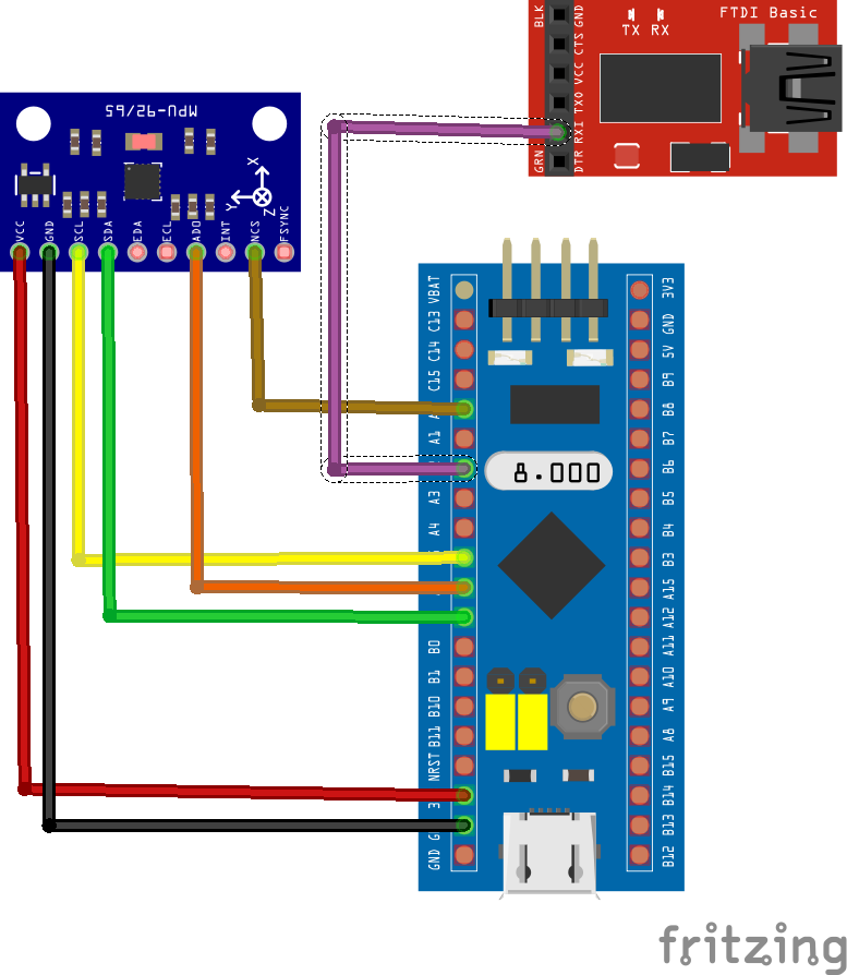
The connection as following:
| MPU9250 | STM32F103 |
| Vcc | 3V3 |
| GND | GND |
| SCL | PA5 |
| SDA | PA7 |
| AD0 | PA6 |
| NCS | PA0 |
Also, FTDI RX pin is connected to PA2 of STM32F103.
5. Code modification:
In order to read from MPU9250 using SPI:
uint8_t MPU9250_accelUpdate(void)
{
	uint8_t data[6]={0x3B|READ_FLAG,0xFF,0xFF,0xFF,0xFF,0xFF};
	cs_low();
	SPI_DMA_Receive(accelBuf, 6);
	SPI_DMA_Transmit(data, 6);
	while(finished_receive()==RX_Inprogress);
	reset_finished();
	cs_high();
	return 0;

}
Declare a buffer which will hold 6 bytes where first byte is the address to be read with read flag and 5 bytes of dummy data to keep the clock generated.
Set the cs pin to low.
start SPI_RX_DMA.
transfer the address to be send with dummy data.
wait until rx finished transfer.
Set CS to high.
Same thing goes to gyroscope:
uint8_t MPU9250_gyroUpdate(void)
{
	uint8_t data[6]={0x43|READ_FLAG,0xFF,0xFF,0xFF,0xFF,0xFF};
	cs_low();
	SPI_DMA_Receive(gyroBuf,6);
	SPI_DMA_Transmit(data, 6);
	while(finished_receive()==RX_Inprogress);
	cs_high();
	reset_finished();
	return 0;
}
In main.c:
#include "spi.h"
#include "uart.h"
#include "MPU9250.h"

int main(void)
{

	spi_DMA_Init();

	uart2_init();

	MPU9250_beginAccel(ACC_FULL_SCALE_16_G);

	MPU9250_beginGyro(GYRO_FULL_SCALE_2000_DPS);

	while(1)
	{
		MPU9250_accelUpdate();
		MPU9250_gyroUpdate();
		printf("---------------------------------------------\r\n");
		printf("Acceleration data %0.3f %0.3f %0.3f \r\n",MPU9250_accelX(),MPU9250_accelY(),MPU9250_accelZ());
		printf("Gyroscope data %0.3f %0.3f %0.3f \r\n",MPU9250_gyroX(),MPU9250_gyroY(),MPU9250_gyroZ());
		printf("---------------------------------------------\r\n");
		for (int i=0;i<100000;i++);
	}
}
6. Code:
You may download the full code from here:
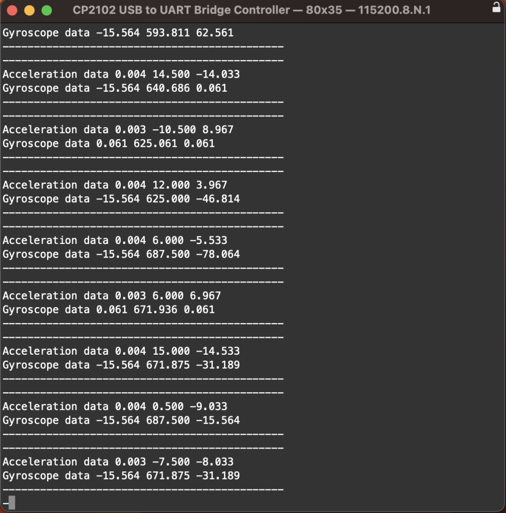
7. Results:
Upload the code and open serial terminal and set baud rate to 115200 and you should get the following:
Happy coding 🙂
Add Comment