In this guide, we shall see how to interface MPU6050 with STM32F4xx.
In this guide, we shall cover the following:
- What is MPU6050.
- Connection.
- Developing the driver.
- Code.
- Results.
1. What is MPU6050:
The MPU-6050™ parts are the world’s first MotionTracking devices designed for the low power, low cost, and high-performance requirements of smartphones, tablets and wearable sensors.
The MPU-6050 incorporates InvenSense’s MotionFusion™ and run-time calibration firmware that enables manufacturers to eliminate the costly and complex selection, qualification, and system level integration of discrete devices in motion-enabled products, guaranteeing that sensor fusion algorithms and calibration procedures deliver optimal performance for consumers.
The MPU-6050 devices combine a 3-axis gyroscope and a 3-axis accelerometer on the same silicon die, together with an onboard Digital Motion Processor™ (DMP™), which processes complex 6-axis MotionFusion algorithms. The device can access external magnetometers or other sensors through an auxiliary master I²C bus, allowing the devices to gather a full set of sensor data without intervention from the system processor. The devices are offered in a 4 mm x 4 mm x 0.9 mm QFN package.

The InvenSense MotionApps™ Platform that comes with the MPU-6050 abstracts motion-based complexities, offloads sensor management from the operating system, and provides a structured set of APIs for application development.
For precision tracking of both fast and slow motions, the parts feature a user-programmable gyro full-scale range of ±250, ±500, ±1000, and ±2000 °/sec (dps), and a user-programmable accelerometer full-scale range of ±2g, ±4g, ±8g, and ±16g. Additional features include an embedded temperature sensor and an on-chip oscillator with ±1% variation over the operating temperature range.
Applications
- BlurFree™ technology (for Video/Still Image Stabilization)
- AirSign™ technology (for Security/Authentication)
- TouchAnywhere™ technology (for “no touch” UI Application Control/Navigation)
- MotionCommand™ technology (for Gesture Short-cuts)
- Motion-enabled game and application framework
- InstantGesture™ iG™ gesture recognition
- Location based services, points of interest, and dead reckoning
- Handset and portable gaming
- Motion-based game controllers
- 3D remote controls for Internet connected DTVs and set top boxes, 3D mice
- Wearable sensors for health, fitness and sports
- Toys
Features:
Gyroscope Features:
The triple-axis MEMS gyroscope in the MPU-60X0 includes a wide range of features:
- Digital-output X-, Y-, and Z-Axis angular rate sensors (gyroscopes) with a user-programmable full-scale range of ±250, ±500, ±1000, and ±2000°/sec
- External sync signal connected to the FSYNC pin supports image, video and GPS synchronization
- Integrated 16-bit ADCs enable simultaneous sampling of gyros
- Enhanced bias and sensitivity temperature stability reduces the need for user calibration
- Improved low-frequency noise performance
- Digitally-programmable low-pass filter
- Gyroscope operating current: 3.6mA
- Standby current: 5µA
- Factory calibrated sensitivity scale factor
- User self-test
Accelerometer Features:
The triple-axis MEMS accelerometer in MPU-60X0 includes a wide range of features:
- Digital-output triple-axis accelerometer with a programmable full scale range of ±2g, ±4g, ±8g and ±16g
- Integrated 16-bit ADCs enable simultaneous sampling of accelerometers while requiring no external multiplexer
- Accelerometer normal operating current: 500µA
- Low power accelerometer mode current: 10µA at 1.25Hz, 20µA at 5Hz, 60µA at 20Hz, 110µA at 40Hz
- Orientation detection and signaling
- Tap detection
- User-programmable interrupts
- High-G interrupt
- User self-test
2. Connection:
The connection as following:
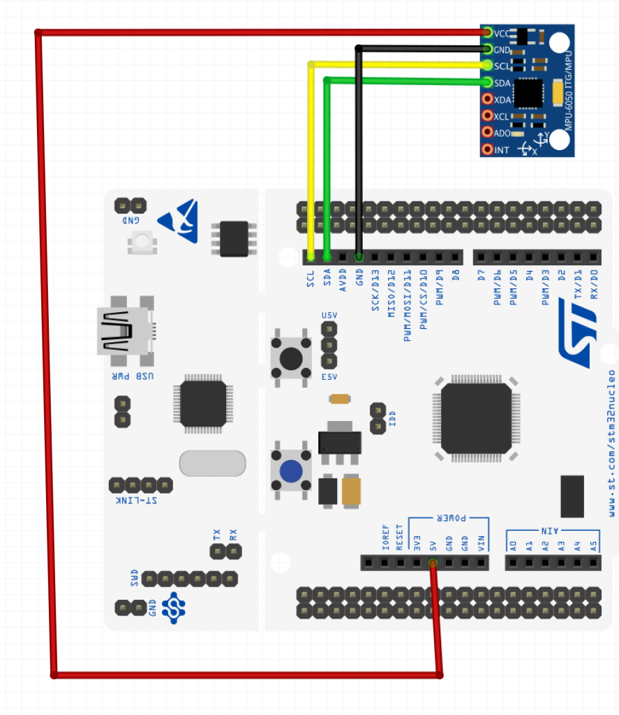
| MPU6050 | STM32F411 |
| Vcc | 5V |
| GND | GND |
| SDA | PB9 |
| SCL | PB8 |
3. Developing the driver:
Before we starting developing the driver, we need the following:
Also, we need uart to transmit data over uart (uart , retargeting printf ).
We start of by creating new source and header file with name of mpu6050.c and mpu6050.h respectively.
Within the header:
Include the following header files
//Header Files
#include "i2c.h"
#include <string.h>
#include <stdbool.h>	//Boolean
#include <math.h>			//Pow()
Define the registers:
//Define Registers
#define MPU_ADDR          0x68

#define WHO_AM_I_REG			0x75
#define PWR_MAGT_1_REG		0x6B
#define CONFIG_REG				0x1A
#define GYRO_CONFIG_REG		0x1B
#define ACCEL_CONFIG_REG	0x1C
#define SMPLRT_DIV_REG		0x19
#define INT_STATUS_REG		0x3A
#define ACCEL_XOUT_H_REG	0x3B
#define TEMP_OUT_H_REG		0x41
#define GYRO_XOUT_H_REG		0x43
#define FIFO_EN_REG 			0x23
#define INT_ENABLE_REG 		0x38
#define I2CMACO_REG 			0x23
#define USER_CNT_REG			0x6A
#define FIFO_COUNTH_REG 	0x72
#define FIFO_R_W_REG 			0x74
Define the struct for MPU configuration:
//1- MPU Configuration
typedef struct
{
	uint8_t ClockSource;
	uint8_t Gyro_Full_Scale;
	uint8_t Accel_Full_Scale;
	uint8_t CONFIG_DLPF;
	bool 		Sleep_Mode_Bit;

}MPU_ConfigTypeDef;
Enum for clock source:
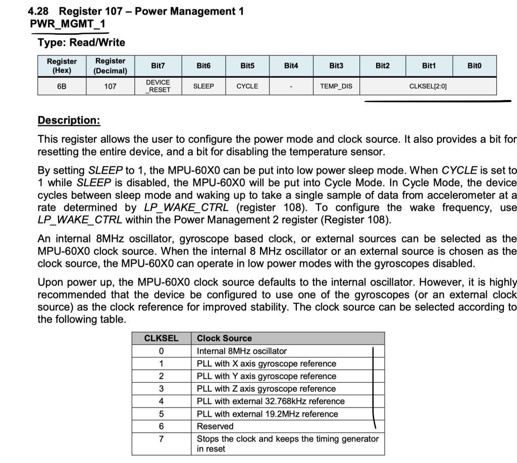
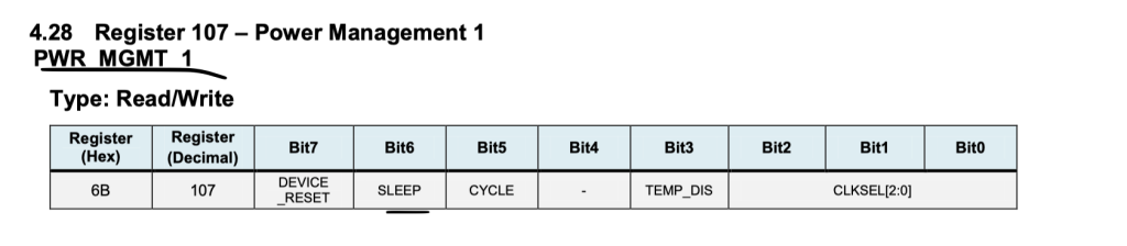
//2- Clock Source ENUM
enum PM_CLKSEL_ENUM
{
	Internal_8MHz 	= 0x00,
	X_Axis_Ref			= 0x01,
	Y_Axis_Ref			= 0x02,
	Z_Axis_Ref			= 0x03,
	Ext_32_768KHz		= 0x04,
	Ext_19_2MHz			= 0x05,
	TIM_GENT_INREST	= 0x07
};
Gyro full scale:
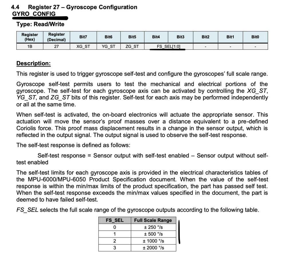
//3- Gyro Full Scale Range ENUM (deg/sec)
enum gyro_FullScale_ENUM
{
	FS_SEL_250 	= 0x00,
	FS_SEL_500 	= 0x01,
	FS_SEL_1000 = 0x02,
	FS_SEL_2000	= 0x03
};
Accelerometer scale:
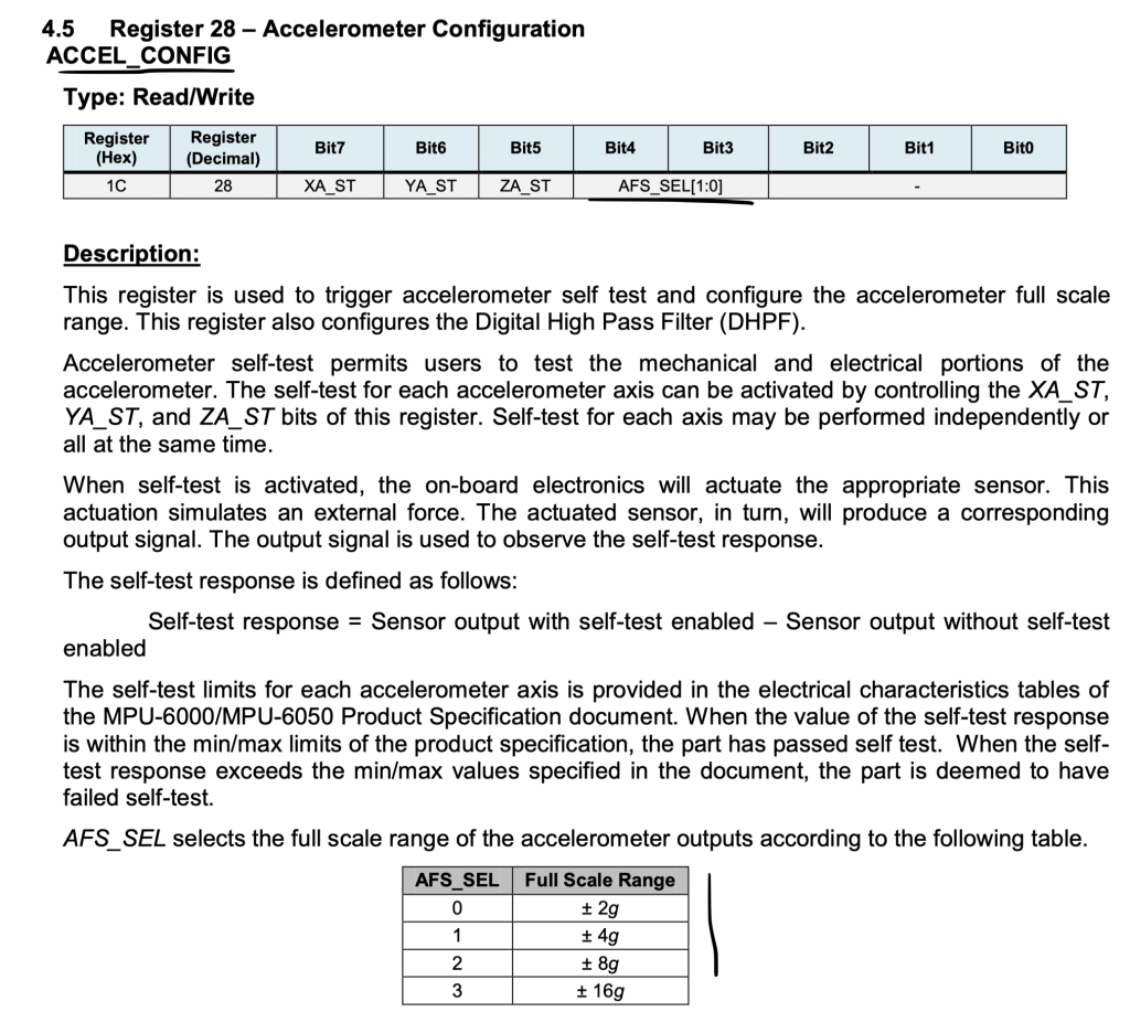
//4- Accelerometer Full Scale Range ENUM (1g = 9.81m/s2)
enum accel_FullScale_ENUM
{
AFS_SEL_2g = 0x00,
AFS_SEL_4g,
AFS_SEL_8g,
AFS_SEL_16g
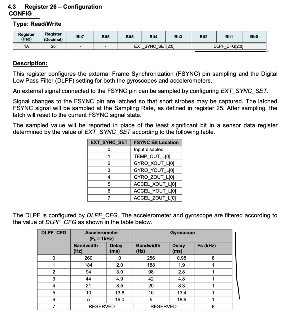
};Digital low pass filter:
enum DLPF_CFG_ENUM
{
	DLPF_260A_256G_Hz = 0x00,
	DLPF_184A_188G_Hz = 0x01,
	DLPF_94A_98G_Hz 	= 0x02,
	DLPF_44A_42G_Hz 	= 0x03,
	DLPF_21A_20G_Hz 	= 0x04,
	DLPF_10_Hz 				= 0x05,
	DLPF_5_Hz 				= 0x06
};
External frame sync:
/6- e external Frame Synchronization ENUM
enum EXT_SYNC_SET_ENUM
{
	input_Disable = 0x00,
	TEMP_OUT_L		= 0x01,
	GYRO_XOUT_L		= 0x02,
	GYRO_YOUT_L		= 0x03,
	GYRO_ZOUT_L		= 0x04,
	ACCEL_XOUT_L	= 0x05,
	ACCEL_YOUT_L	= 0x06,
	ACCEL_ZOUT_L	= 0x07
};
Raw data struct:
//7. Raw data typedef
typedef struct
{
	int16_t x;
	int16_t y;
	int16_t z;
}RawData_Def;
Scaled data struct:
//8. Scaled data typedef
typedef struct
{
	float x;
	float y;
	float z;
}ScaledData_Def;
Function prototypes:
//Function Prototype

//2- i2c Read
void I2C_Read(uint8_t ADDR, uint8_t *i2cBuf, uint8_t NofData);
//3- i2c Write 8 Bit
void I2C_Write8(uint8_t ADDR, uint8_t data);
//4- MPU6050 Initialaztion Configuration
void MPU6050_Config(MPU_ConfigTypeDef *config);
//5- Get Sample Rate Divider
uint8_t MPU6050_Get_SMPRT_DIV(void);
//6- Set Sample Rate Divider
void MPU6050_Set_SMPRT_DIV(uint8_t SMPRTvalue);
//7- External Frame Sync.
uint8_t MPU6050_Get_FSYNC(void);
//8- Set External Frame Sync.
void MPU6050_Set_FSYNC(enum EXT_SYNC_SET_ENUM ext_Sync);
//9- Get Accel Raw Data
void MPU6050_Get_Accel_RawData(RawData_Def *rawDef);//************
//10- Get Accel scaled data
void MPU6050_Get_Accel_Scale(ScaledData_Def *scaledDef);//***********
//11- Get Accel calibrated data
void MPU6050_Get_Accel_Cali(ScaledData_Def *CaliDef);
//12- Get Gyro Raw Data
void MPU6050_Get_Gyro_RawData(RawData_Def *rawDef);
//13- Get Gyro scaled data
void MPU6050_Get_Gyro_Scale(ScaledData_Def *scaledDef);
//14- Accel Calibration
void _Accel_Cali(float x_min, float x_max, float y_min, float y_max, float z_min, float z_max);
Hence, the entire header file:
//Header Files
#include "i2c.h"
#include <string.h>
#include <stdbool.h>	//Boolean
#include <math.h>			//Pow()

//Define Registers
#define MPU_ADDR          0x68

#define WHO_AM_I_REG			0x75
#define PWR_MAGT_1_REG		0x6B
#define CONFIG_REG				0x1A
#define GYRO_CONFIG_REG		0x1B
#define ACCEL_CONFIG_REG	0x1C
#define SMPLRT_DIV_REG		0x19
#define INT_STATUS_REG		0x3A
#define ACCEL_XOUT_H_REG	0x3B
#define TEMP_OUT_H_REG		0x41
#define GYRO_XOUT_H_REG		0x43
#define FIFO_EN_REG 			0x23
#define INT_ENABLE_REG 		0x38
#define I2CMACO_REG 			0x23
#define USER_CNT_REG			0x6A
#define FIFO_COUNTH_REG 	0x72
#define FIFO_R_W_REG 			0x74

//TypeDefs and Enums
//1- MPU Configuration
typedef struct
{
	uint8_t ClockSource;
	uint8_t Gyro_Full_Scale;
	uint8_t Accel_Full_Scale;
	uint8_t CONFIG_DLPF;
	bool 		Sleep_Mode_Bit;

}MPU_ConfigTypeDef;

//2- Clock Source ENUM
enum PM_CLKSEL_ENUM
{
	Internal_8MHz 	= 0x00,
	X_Axis_Ref			= 0x01,
	Y_Axis_Ref			= 0x02,
	Z_Axis_Ref			= 0x03,
	Ext_32_768KHz		= 0x04,
	Ext_19_2MHz			= 0x05,
	TIM_GENT_INREST	= 0x07
};

//3- Gyro Full Scale Range ENUM (deg/sec)
enum gyro_FullScale_ENUM
{
	FS_SEL_250 	= 0x00,
	FS_SEL_500 	= 0x01,
	FS_SEL_1000 = 0x02,
	FS_SEL_2000	= 0x03
};


//4- Accelerometer Full Scale Range ENUM (1g = 9.81m/s2)
enum accel_FullScale_ENUM
{
	AFS_SEL_2g	= 0x00,
	AFS_SEL_4g,
	AFS_SEL_8g,
	AFS_SEL_16g
};

//5- Digital Low Pass Filter ENUM
enum DLPF_CFG_ENUM
{
	DLPF_260A_256G_Hz = 0x00,
	DLPF_184A_188G_Hz = 0x01,
	DLPF_94A_98G_Hz 	= 0x02,
	DLPF_44A_42G_Hz 	= 0x03,
	DLPF_21A_20G_Hz 	= 0x04,
	DLPF_10_Hz 				= 0x05,
	DLPF_5_Hz 				= 0x06
};
//6- e external Frame Synchronization ENUM
enum EXT_SYNC_SET_ENUM
{
	input_Disable = 0x00,
	TEMP_OUT_L		= 0x01,
	GYRO_XOUT_L		= 0x02,
	GYRO_YOUT_L		= 0x03,
	GYRO_ZOUT_L		= 0x04,
	ACCEL_XOUT_L	= 0x05,
	ACCEL_YOUT_L	= 0x06,
	ACCEL_ZOUT_L	= 0x07
};

//7. Raw data typedef
typedef struct
{
	int16_t x;
	int16_t y;
	int16_t z;
}RawData_Def;

//8. Scaled data typedef
typedef struct
{
	float x;
	float y;
	float z;
}ScaledData_Def;


//Function Prototype

//2- i2c Read
void I2C_Read(uint8_t ADDR, uint8_t *i2cBuf, uint8_t NofData);
//3- i2c Write 8 Bit
void I2C_Write8(uint8_t ADDR, uint8_t data);
//4- MPU6050 Initialaztion Configuration
void MPU6050_Config(MPU_ConfigTypeDef *config);
//5- Get Sample Rate Divider
uint8_t MPU6050_Get_SMPRT_DIV(void);
//6- Set Sample Rate Divider
void MPU6050_Set_SMPRT_DIV(uint8_t SMPRTvalue);
//7- External Frame Sync.
uint8_t MPU6050_Get_FSYNC(void);
//8- Set External Frame Sync.
void MPU6050_Set_FSYNC(enum EXT_SYNC_SET_ENUM ext_Sync);
//9- Get Accel Raw Data
void MPU6050_Get_Accel_RawData(RawData_Def *rawDef);//************
//10- Get Accel scaled data
void MPU6050_Get_Accel_Scale(ScaledData_Def *scaledDef);//***********
//11- Get Accel calibrated data
void MPU6050_Get_Accel_Cali(ScaledData_Def *CaliDef);
//12- Get Gyro Raw Data
void MPU6050_Get_Gyro_RawData(RawData_Def *rawDef);
//13- Get Gyro scaled data
void MPU6050_Get_Gyro_Scale(ScaledData_Def *scaledDef);
//14- Accel Calibration
void _Accel_Cali(float x_min, float x_max, float y_min, float y_max, float z_min, float z_max);
Thats all for header file.
The source file:
Include the following:
#include "MPU6050.h"
#include "i2c.h"
#include "time_base.h"
Static variable for the library:
//2- Accel & Gyro Scaling Factor
static float accelScalingFactor, gyroScalingFactor;
//3- Bias variables
static float A_X_Bias = 0.0f;
static float A_Y_Bias = 0.0f;
static float A_Z_Bias = 0.0f;

static int16_t GyroRW[3];
MPU configuration:
void MPU6050_Config(MPU_ConfigTypeDef *config)
{
	uint8_t Buffer = 0;
	//Clock Source
	//Reset Device

	i2c_writeByte(MPU_ADDR, PWR_MAGT_1_REG, 0x80);

	delay(100);

	Buffer = config ->ClockSource & 0x07; //change the 7th bits of register

	Buffer |= (config ->Sleep_Mode_Bit << 6) &0x40; // change only the 7th bit in the register

	i2c_writeByte(MPU_ADDR,PWR_MAGT_1_REG, Buffer);

	delay(100); // should wait 10ms after changeing the clock setting.

	//Set the Digital Low Pass Filter
	Buffer = 0;

	Buffer = config->CONFIG_DLPF & 0x07;

	i2c_writeByte(MPU_ADDR,CONFIG_REG, Buffer);

	//Select the Gyroscope Full Scale Range
	Buffer = 0;

	Buffer = (config->Gyro_Full_Scale << 3) & 0x18;

	i2c_writeByte(MPU_ADDR,GYRO_CONFIG_REG, Buffer);

	//Select the Accelerometer Full Scale Range
	Buffer = 0;

	Buffer = (config->Accel_Full_Scale << 3) & 0x18;

	i2c_writeByte(MPU_ADDR,ACCEL_CONFIG_REG, Buffer);

	//Set SRD To Default
	MPU6050_Set_SMPRT_DIV(0x04);


	//Accelerometer Scaling Factor, Set the Accelerometer and Gyroscope Scaling Factor
	switch (config->Accel_Full_Scale)
	{
		case AFS_SEL_2g:
			accelScalingFactor = (2000.0f/32768.0f);
			break;

		case AFS_SEL_4g:
			accelScalingFactor = (4000.0f/32768.0f);
				break;

		case AFS_SEL_8g:
			accelScalingFactor = (8000.0f/32768.0f);
			break;

		case AFS_SEL_16g:
			accelScalingFactor = (16000.0f/32768.0f);
			break;

		default:
			break;
	}
	//Gyroscope Scaling Factor
	switch (config->Gyro_Full_Scale)
	{
		case FS_SEL_250:
			gyroScalingFactor = 250.0f/32768.0f;
			break;

		case FS_SEL_500:
				gyroScalingFactor = 500.0f/32768.0f;
				break;

		case FS_SEL_1000:
			gyroScalingFactor = 1000.0f/32768.0f;
			break;

		case FS_SEL_2000:
			gyroScalingFactor = 2000.0f/32768.0f;
			break;

		default:
			break;
	}

}
Get the sample rate:
//5- Get Sample Rate Divider
uint8_t MPU6050_Get_SMPRT_DIV(void)
{
	uint8_t Buffer = 0;

	i2c_readByte(MPU_ADDR,SMPLRT_DIV_REG,&Buffer);

	return Buffer;
}
Set the sample rate:
//6- Set Sample Rate Divider
void MPU6050_Set_SMPRT_DIV(uint8_t SMPRTvalue)
{
	i2c_writeByte(MPU_ADDR,SMPLRT_DIV_REG, SMPRTvalue);
}
Get eh external FYSNC:
uint8_t MPU6050_Get_FSYNC(void)
{
	uint8_t Buffer = 0;

	i2c_readByte(MPU_ADDR,CONFIG_REG, &Buffer);
	Buffer &= 0x38;
	return (Buffer>>3);
}
Set the FYSNC:
//8- Set External Frame Sync.
void MPU6050_Set_FSYNC(enum EXT_SYNC_SET_ENUM ext_Sync)
{
	uint8_t Buffer = 0;
	i2c_readByte(MPU_ADDR,CONFIG_REG, &Buffer);
	Buffer &= ~0x38;

	Buffer |= (ext_Sync <<3);
	i2c_writeByte(MPU_ADDR,CONFIG_REG, Buffer);

}
Get the raw acceleration data:
//9- Get Accel Raw Data
void MPU6050_Get_Accel_RawData(RawData_Def *rawDef)
{
	uint8_t state;
	uint8_t AcceArr[6], GyroArr[6];

	i2c_readByte(MPU_ADDR,INT_STATUS_REG, &state);


	if((state&&0x01))
	{
		i2c_ReadMulti(MPU_ADDR,ACCEL_XOUT_H_REG, 6,AcceArr);

		//Accel Raw Data
		rawDef->x = ((AcceArr[0]<<8) + AcceArr[1]); // x-Axis
		rawDef->y = ((AcceArr[2]<<8) + AcceArr[3]); // y-Axis
		rawDef->z = ((AcceArr[4]<<8) + AcceArr[5]); // z-Axis
		//Gyro Raw Data
		i2c_ReadMulti(MPU_ADDR,GYRO_XOUT_H_REG, 6,GyroArr);
		GyroRW[0] = ((GyroArr[0]<<8) + GyroArr[1]);
		GyroRW[1] = (GyroArr[2]<<8) + GyroArr[3];
		GyroRW[2] = ((GyroArr[4]<<8) + GyroArr[5]);
	}
}
Get the acceleration data:
//10- Get Accel scaled data (g unit of gravity, 1g = 9.81m/s2)
void MPU6050_Get_Accel_Scale(ScaledData_Def *scaledDef)
{

	RawData_Def AccelRData;
	MPU6050_Get_Accel_RawData(&AccelRData);

	//Accel Scale data
	scaledDef->x = ((AccelRData.x+0.0f)*accelScalingFactor)/1000;
	scaledDef->y = ((AccelRData.y+0.0f)*accelScalingFactor)/1000;
	scaledDef->z = ((AccelRData.z+0.0f)*accelScalingFactor)/1000;
}
Get the acceleration calibrated data:
//11- Get Accel calibrated data
void MPU6050_Get_Accel_Cali(ScaledData_Def *CaliDef)
{
	ScaledData_Def AccelScaled;
	MPU6050_Get_Accel_Scale(&AccelScaled);

	//Accel Scale data
	CaliDef->x = (AccelScaled.x) - A_X_Bias; // x-Axis
	CaliDef->y = (AccelScaled.y) - A_Y_Bias;// y-Axis
	CaliDef->z = (AccelScaled.z) - A_Z_Bias;// z-Axis
}
Get the Gyro data:
//12- Get Gyro Raw Data
void MPU6050_Get_Gyro_RawData(RawData_Def *rawDef)
{

	//Accel Raw Data
	rawDef->x = GyroRW[0];
	rawDef->y = GyroRW[1];
	rawDef->z = GyroRW[2];

}

//13- Get Gyro scaled data
void MPU6050_Get_Gyro_Scale(ScaledData_Def *scaledDef)
{
	RawData_Def myGyroRaw;
	MPU6050_Get_Gyro_RawData(&myGyroRaw);

	//Gyro Scale data
	scaledDef->x = (myGyroRaw.x)*gyroScalingFactor; // x-Axis
	scaledDef->y = (myGyroRaw.y)*gyroScalingFactor; // y-Axis
	scaledDef->z = (myGyroRaw.z)*gyroScalingFactor; // z-Axis
}
Calibrate the acceleration:
//14- Accel Calibration
void _Accel_Cali(float x_min, float x_max, float y_min, float y_max, float z_min, float z_max)
{
	//1* X-Axis calibrate
	A_X_Bias		= (x_max + x_min)/2.0f;

	//2* Y-Axis calibrate
	A_Y_Bias		= (y_max + y_min)/2.0f;

	//3* Z-Axis calibrate
	A_Z_Bias		= (z_max + z_min)/2.0f;
}
In main.c:
#include "i2c.h"
#include "time_base.h"
#include "uart.h"
#include "stdio.h"
#include "MPU6050.h"
#define rate 300
uint32_t previous;
int main(void)
{
Ticks_Init(16000000);
uart2_rxtx_init();
i2c_init();
MPU_ConfigTypeDef myConfig;
myConfig.Accel_Full_Scale = AFS_SEL_4g;
myConfig.ClockSource = Internal_8MHz;
myConfig.CONFIG_DLPF = DLPF_184A_188G_Hz;
myConfig.Sleep_Mode_Bit = 0;
myConfig.Gyro_Full_Scale = FS_SEL_500;
MPU6050_Config(&myConfig);
ScaledData_Def meAccel;
while(1)
{
MPU6050_Get_Accel_Scale(&meAccel);
if(get_Ticks()-previous >rate)
{
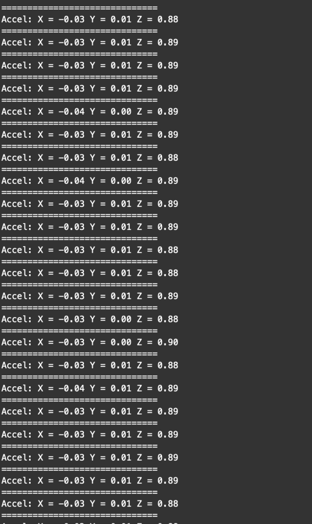
printf("Accel: X = %.2f Y = %.2f Z = %.2f\r\n", meAccel.x, meAccel.y, meAccel.z);
printf("==============================\r\n");
previous=get_Ticks();
}
}
}
For the configuration:
First, Set thee acceleration scale for 4G:
myConfig.Accel_Full_Scale = AFS_SEL_4g;
Set the clock to be internal 8MHz:
myConfig.ClockSource = Internal_8MHz;
Configure the filter:
myConfig.CONFIG_DLPF = DLPF_184A_188G_Hz;
Exit from sleep mode:
myConfig.Sleep_Mode_Bit = 0;
Set the gyro scale:
myConfig.Gyro_Full_Scale = FS_SEL_500;
Pass the data structure to MPU configuration function as following:
MPU6050_Config(&myConfig);
4. Code:
You may download the code from here:
5. Results:
Upload the code to your F411RE Nucleo and open serial monitor and set the buadrare to 115200:
Happy coding 🙂
2 Comments
How do you get the gyro values? this code only allows the accel values. Thank you.
There are functions to read the gyroscope.
You can use them.
Add Comment