
In this guide, we shall see how the internal RTC of STM32F4 is working and what features it holds and in part2, we shall configure the RTC and display the time and date on Liquid Crystal Display (LCD).
In this guide, we will cover the following:
- What is RTC.
- Feature of internal RTC.
- Block diagram.
- LCD connection.
- Environment download.
1. What is RTC:
What Does Real-Time Clock (RTC) Mean?
A real-time clock (RTC) is a computer clock, usually in the form of an integrated circuit that is solely built for keeping time. Naturally, it counts hours, minutes, seconds, months, days and even years. RTCs can be found running in personal computers, embedded systems and servers, and are present in any electronic device that may require accurate time keeping. Being able to still function even when the computer is powered down through a battery or independently from the system’s main power is fundamental.
Explaining Real-Time Clock (RTC)
RTCs must accurately keep time, even when the device is powered off because, it is often used as a trigger for turning the device on or triggering events such as alarm clocks. RTC ICs run on an alternate power source, which allows it to continually operate under low power or even when the computer is turned off. ICs on older systems utilize lithium batteries, whereas newer systems make use of auxiliary batteries or supercapacitors. RTC ICs that use supercapacitors are rechargeable and can be soldered. But in most consumer-grade motherboards, the RTC is powered by a single battery that, when removed, resets the RTC to its starting point.
RTC ICs regulate time with the use of a crystal oscillator and do not rely on clock signals like most hardware clocks. Aside from being responsible for the timing function of the system and its clock, RTC ICs ensure that all processes occurring in the system are appropriately synchronized. Although some may argue that this is a job for the system clock, the system clock is actually dependent on the RTC, making the RTC indirectly responsible for synchronization.
An RTC battery should last for three to five years or more. RTCs are essential; if the battery fails, it must be replaced to ensure continued operation. A dead battery can be diagnosed with an error message at startup or if the user finds that the clock or the setup configuration has become corrupted, flaky or odd.
Benefits of RTCs include:
- RTC ICs have proved to be more precise than other methods — like programming the timer of the controller.
- It frees the main system from time-critical tasks.
- It has low power consumption and improved frequency stability.
2. Feature of Internal RTC:
The RTC unit main features are the following:
• Calendar with subseconds, seconds, minutes, hours (12 or 24 format), day (day of week), date (day of month), month, and year.
• Daylight saving compensation programmable by software.
• Two programmable alarms with interrupt function. The alarms can be triggered by any combination of the calendar fields.
• Automatic wakeup unit generating a periodic flag that triggers an automatic wakeup interrupt.
• Reference clock detection: a more precise second source clock (50 or 60 Hz) can be used to enhance the calendar precision.
• Accurate synchronization with an external clock using the subsecond shift feature.
• Maskable interrupts/events:
– Alarm A
– Alarm B
– Wakeup interrupt
– Timestamp
– Tamper detection
• Digital calibration circuit (periodic counter correction)
– 5 ppm accuracy
– 0.95 ppm accuracy, obtained in a calibration window of several seconds
• Timestamp function for event saving (1 event)
• Tamper detection:
– Tamper event with configurable filter and internal pull-up.
• 20 backup registers (80 bytes). The backup registers are reset when a tamper detection event occurs.
• Alternate function output (RTC_OUT) which selects one of the following two outputs:
– RTC_CALIB: 512 Hz or 1 Hz clock output (with an LSE frequency of 32.768 kHz).
This output is enabled by setting the COE bit in the RTC_CR register. It is routed to the device RTC_AF1 function.
– RTC_ALARM (Alarm A, Alarm B or wakeup).
This output is selected by configuring the OSEL[1:0] bits in the RTC_CR register. It is routed to the device RTC_AF1 function.
• RTC additional function inputs:
– RTC_TS: timestamp event detection. It is routed to the device RTC_AF1 function.
– RTC_TAMP1: TAMPER1 event detection. It is routed to the device RTC_AF1 function.
– RTC_REFIN: reference clock input (usually the mains, 50 or 60 Hz).
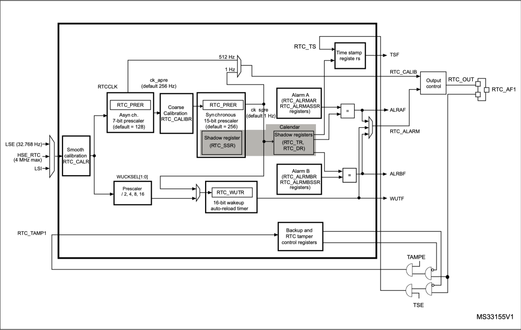
3. Block diagram:
4. LCD Connection:
In this guide, we need the following part:
- LCD (16×2 or 20×4)
- PCF8574 for LCD module
- STM32F411RE Nucelo-64
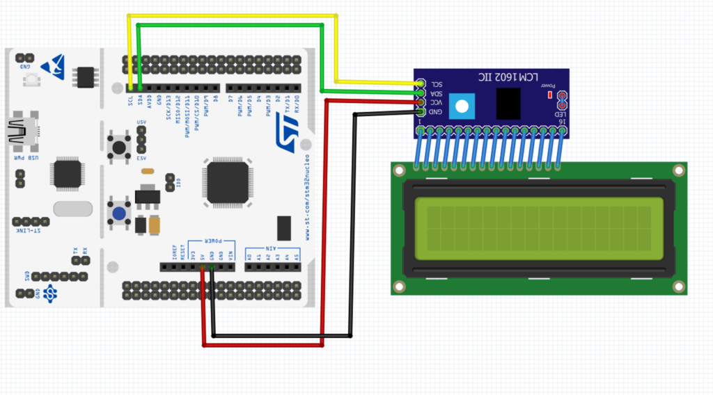
No other components needed since the RTC is built-in.
For more information, refer to this guide.
5. Environment download:
Since we will develop the code from scratch, you may download the code working environment from here:
See you in next part.
Happy coding 🙂
Add Comment