
In this guide, we shall use UART in TX mode to send single character each time.
In this cover, we will cover the following:
- UART.
- Configuring pins to work in UART mode.
- Configure the UART.
- Send character.
- Code.
- Results.
1. UART:
To transfer data, computers adopt two method: serial and parallel. In serial communication data is sent a bit at a time (1 line)while in parallel communication 8 or more lines are often used to transfer data. The UART is a form of serial communication. When distance is short, digital signal can be transferred as it is on a single wire and require no modulation. This is how PC keyboard transfer data between the keyboard and motherboard. For long distances like telephone lines, serial data communication requires a modem to modulate.We will not go into the details of this in this lesson, this shall be left for subsequent lessons.
Synchronous vs. Asynchronous
Serial communication operate in two ways : synchronous and asynchronous. In the synchronous mode, a block of data is sent at a time while in the asynchronous mode, a single byte of data is sent at a time. It is possible to write code to provide both the synchronous and asynchronous serial communication functions however this could turn out tedious and over complicated therefore, special chips are manufactured to perform these functions. When these chips are added to a microcontroller, they become known as Serial Communication Interface (SCI). The chip that provides the the asynchronous communication (UART) is the main theme of this lesson. The chip for synchronous communication is known as the USART and shall left for another lesson.
Asynchronous Communication Data Framing
The data is received in zeros and ones format, in order to make sense of the data, the sender and the receiver must agree on a set of rules i.e. a protocol, on how data is packed, how many bits constitute a character and when data begins and ends.
The Protocol
- Start and Stop bits
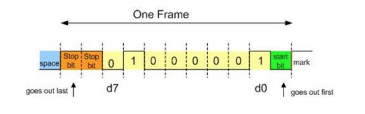
Asynchronous serial communication is widely used in character transfer. Each character is packed between start and stop bits. This is known as the framing.
start bit : Always 1 bit, value is always 0
stop bit: 1 or 2 bits, value is always 1
Lets take an example. Lets say we are transferring ASCII character ‘A’
its binary code is 0100 0001 and 0x41 in hex.Furthermore, it is framed between a start bit and 2 stop bits. This is what its frame will look like.
2. Parity bit
Some systems require parity bit in order to maintain data integrity.The parity bit of a character byte is included in the data frame after the stop bit(s).
3.Rate of data transfer : Baud rate/bps
We shall explain this concept with an example. Lets say we are asked to calculate the number of bits used and time taken in transferring 50 pages of text, each with 80×25 characters. Assuming 8 bits per character and 1 stop bit
solution
For each character a total of 10 bits is used ( 1 start bit, 8 bits character, 1 stop bit).
Therefore total number of bits = 80 x 25 x10 = 20,000 bits per page
50 pages implies, 50×20,000 = 1,000,000 bits.
Therefore it will take 1 million bits to transfer this information.
The time it takes to transfer the entire data using
a. 9600 baudrate implies, 1,000,000 / 9600 = 204 seconds
b. 57,600 baudrate implies 1,000,000 /57,600 = 17 seconds
Baudrate simply means the transfer of bits per second. There are various standardized baudrate we can choose from when we program our serial communication devices. The key thing is, both communication devices must have the same baudrate. We shall see this later on in our example code.
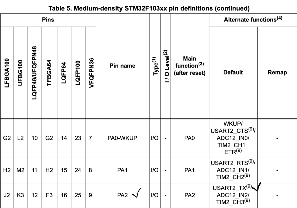
2. Configure pins to work in UART mode:
First, we need to find which pins are related to UART, from the datasheet, we can find that PA2 is for UART2_TX and PA3 is for UART2_RX. Since we are only interested in TX, we shall use PA2 as TX pins.
We start off by enabling clock access to GPIOA as following:
//enable clock access to GPIOA
RCC->APB2ENR|=RCC_APB2ENR_IOPAEN;
Then enable clock access to alternate function:
	//Enable clock access to alternate function
	RCC->APB2ENR|=RCC_APB2ENR_AFIOEN;
Then we need to set the pin as following:
- Output with maximum speed of 50MHz.
- Alternate function output Push-pull.
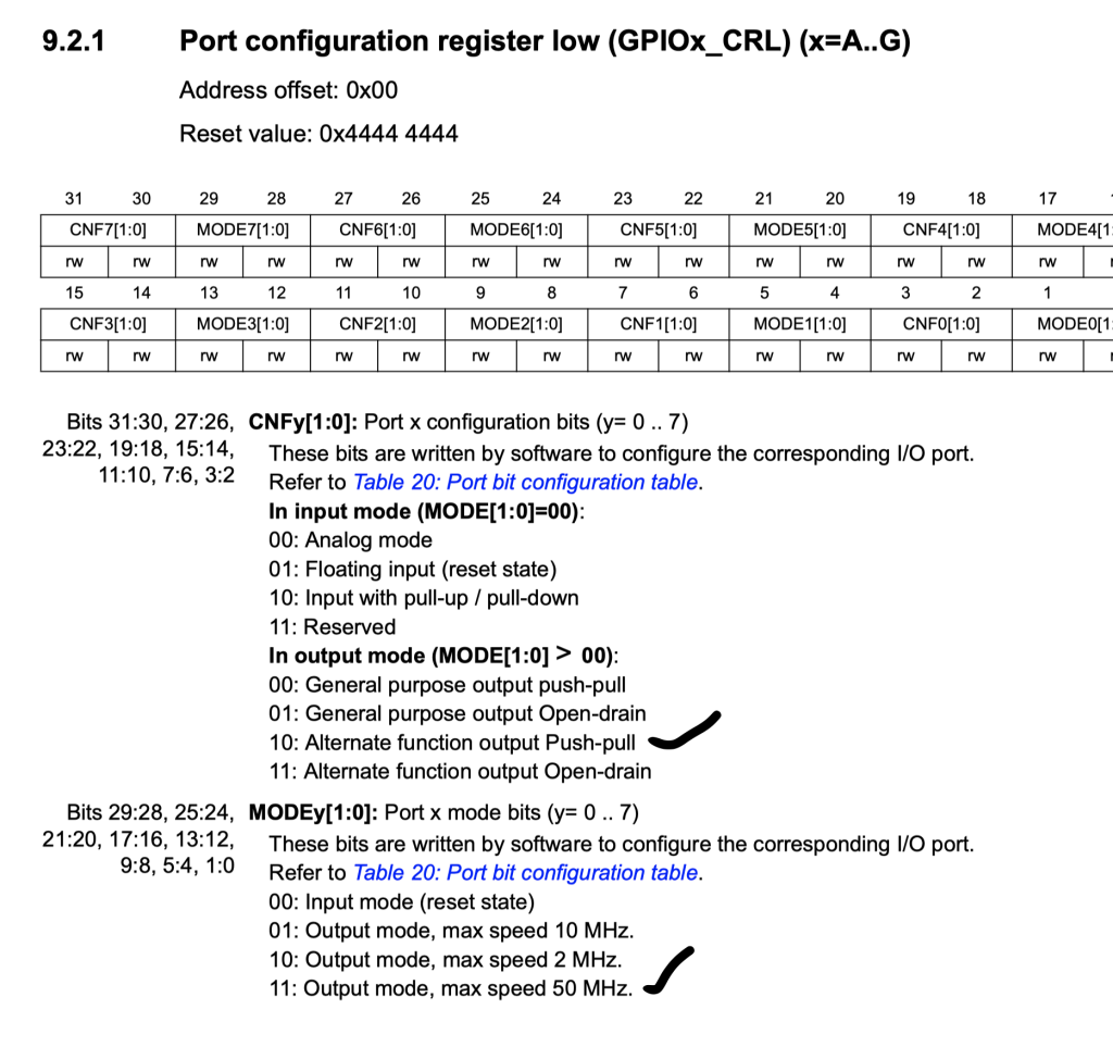
	/*Configure PA2 as output maximum speed to 50MHz
	 * and alternate output push-pull mode*/
	GPIOA->CRL|=GPIO_CRL_MODE2;

	GPIOA->CRL|=GPIO_CRL_CNF2_1;
	GPIOA->CRL&=~GPIO_CRL_CNF2_0;
Finally, don’t remap the pins:
/*Don't remap the pins*/
AFIO->MAPR&=~AFIO_MAPR_USART2_REMAP;
3. Configure the UART:
First we enable clock access to UART2:
UART2 is connected to APB1:
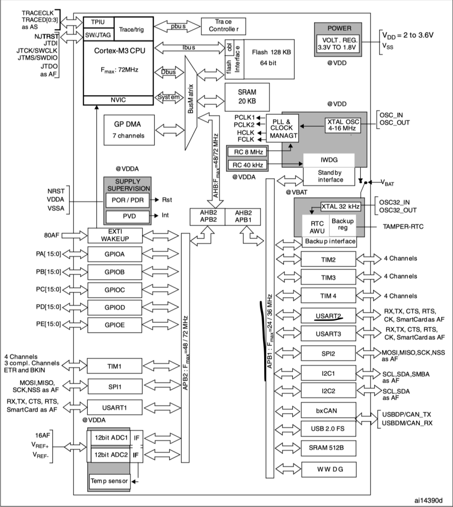
	//enable clock access to USART2

	RCC->APB1ENR|=RCC_APB1ENR_USART2EN;
Then enable UART_TX:
	//Transmit Enable
	USART2->CR1 |= USART_CR1_TE;
Set the baudrate using the following two functions:
static uint16_t compute_uart_bd(uint32_t PeriphClk, uint32_t BaudRate)
{
	return ((PeriphClk + (BaudRate/2U))/BaudRate);
}


static void uart_set_baudrate(USART_TypeDef *USARTx, uint32_t PeriphClk,  uint32_t BaudRate)
{
	USARTx->BRR =  compute_uart_bd(PeriphClk,BaudRate);
}
Set the buadrate to be 115200 and since the peripheral clock speed is 8MHz:
#define Perpher_CLK 8000000
#define Baudrate	115200

	/*Set baudrate */
	uart_set_baudrate(USART2,Perpher_CLK,Baudrate);
Finally enable the module:
	//Enable UART
	USART2->CR1 |= USART_CR1_UE;
4. Sending single character:
In order to send a single character, we need the following two steps:
- Wait until the transmit data register is empty.
- Push the character to the data register.
To find if the transmit data register is empty, we need to check TXE bit from SR register:
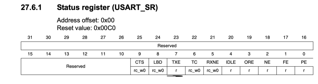
void uart2_write(int ch)
{
  /*Make sure the transmit data register is empty*/
	while(!(USART2->SR & USART_SR_TXE)){}

  /*Write to transmit data register*/
	USART2->DR	=  (ch & 0xFF);
}
5. Code:
The entire code as following:
#include "stm32f1xx.h"


#define Perpher_CLK 8000000
#define Baudrate	115200


static uint16_t compute_uart_bd(uint32_t PeriphClk, uint32_t BaudRate)
{
	return ((PeriphClk + (BaudRate/2U))/BaudRate);
}


static void uart_set_baudrate(USART_TypeDef *USARTx, uint32_t PeriphClk,  uint32_t BaudRate)
{
	USARTx->BRR =  compute_uart_bd(PeriphClk,BaudRate);
}


void uart2_write(int ch)
{
  /*Make sure the transmit data register is empty*/
	while(!(USART2->SR & USART_SR_TXE)){}

  /*Write to transmit data register*/
	USART2->DR	=  (ch & 0xFF);
}


int main(void)
{

	/*UART2 Pin configures*/

	//enable clock access to GPIOA
	RCC->APB2ENR|=RCC_APB2ENR_IOPAEN;
	//Enable clock access to alternate function
	RCC->APB2ENR|=RCC_APB2ENR_AFIOEN;

	/*Confgiure PA2 as output maximum speed to 50MHz
	 * and alternate output push-pull mode*/
	GPIOA->CRL|=GPIO_CRL_MODE2;

	GPIOA->CRL|=GPIO_CRL_CNF2_1;
	GPIOA->CRL&=~GPIO_CRL_CNF2_0;


	/*Don't remap the pins*/
	AFIO->MAPR&=~AFIO_MAPR_USART2_REMAP;


	/*USART2 configuration*/

	//enable clock access to USART2

	RCC->APB1ENR|=RCC_APB1ENR_USART2EN;

	//Transmit Enable
	USART2->CR1 |= USART_CR1_TE;

	/*Set baudrate */
	uart_set_baudrate(USART2,Perpher_CLK,Baudrate);
	//Enable UART
	USART2->CR1 |= USART_CR1_UE;


	while(1)
	{
		uart2_write('Y');
		uart2_write('\r');
		uart2_write('\n');


	}
}
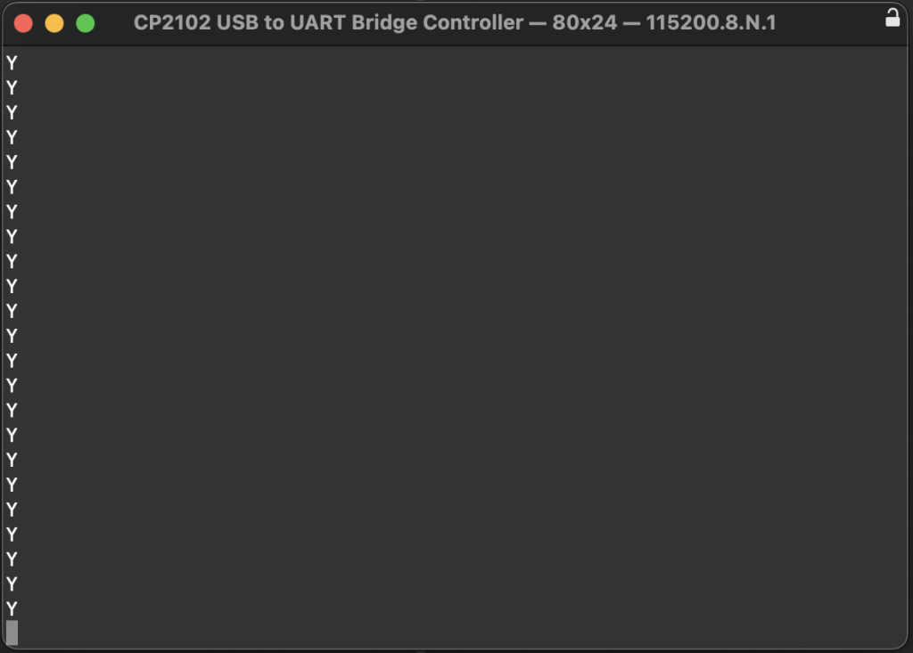
6. Results:
After connecting TTL-USB converter and RX pin of the converter to PA2 and open terminal program and set the buadrate to 115200 and you should get this:
Happy coding 🙂
Add Comment