In the previous guide(here) we saw how to configure the I2C to write to a slave device, n this guide, we shall see how to configure I2C in STM32L053 to write to a specific register of an I2C device (DS3231 in this case) using DMA.
In this guide, we shall cover the following:
- I2C with DMA configuration.
- I2C write DMA.
- Code.
- Demo.
1. I2C with DMA Configuration:
We start off with configuring I2C as shown in the previous guide:
	RCC->IOPENR|=RCC_IOPENR_GPIOBEN;
	GPIOB->MODER&=~(GPIO_MODER_MODE8|GPIO_MODER_MODE9);
	GPIOB->MODER|=GPIO_MODER_MODE8_1|GPIO_MODER_MODE9_1;
	GPIOB->OTYPER|=GPIO_OTYPER_OT_8|GPIO_OTYPER_OT_9;
	GPIOB->OSPEEDR|=GPIO_OSPEEDER_OSPEED8_0|GPIO_OSPEEDER_OSPEED8_1|GPIO_OSPEEDER_OSPEED9_0|GPIO_OSPEEDER_OSPEED9_1;
	GPIOB->AFR[1]|=(AF04<<0)|(AF04<<4);

	RCC->APB1ENR|=RCC_APB1ENR_I2C1EN;
	I2C1->CR1 &=~I2C_CR1_PE;
	I2C1->TIMINGR=timing;
After that, we configure DMA.
In order to configure the DMA, we need to enable clock access to the DMA1.
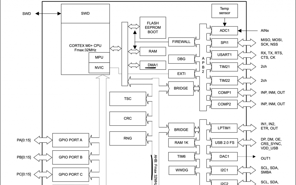
Since STM32L053 has only single DMA and it is connected to AHB Bus, we can enable clock access to DMA1 as following:
RCC->AHBENR|=RCC_AHBENR_DMA1EN;
Now, we need to check which channel is responsible for I2C1_TX.
From the reference manual, we can check DMA request for each channel:
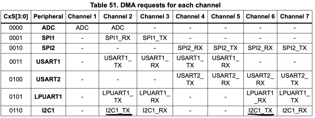
We can see that we have channel2 and channel6 for I2C1_TX, in this guide, channel6 shall be used.
After enabling clock access to DMA1, we need configure channel6 with the following parameters:
- Memory increment mode.
- Direction read from memory.
- Transfer complete interrupt enable.
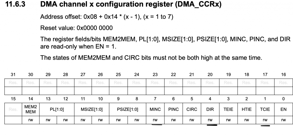
DMA1_Channel6->CCR |=DMA_CCR_MINC|DMA_CCR_DIR|DMA_CCR_TCIE;
Set the peripheral address to be the TXDR:
DMA1_Channel6->CPAR= (uint32_t)&I2C1->TXDR;
Enable the DMA1_Channel interrupt in NVIC:
Channel4 through 7 share the same interrupt handler
NVIC_EnableIRQ(DMA1_Channel4_5_6_7_IRQn);
Set Channel6 to be I2C:
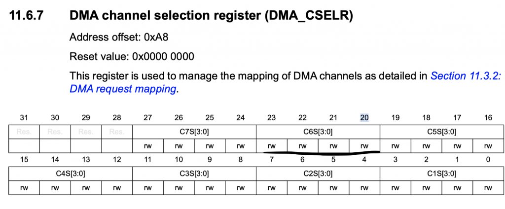
#define DMA_CSELR  (*(volatile unsigned int *)(0x400200a8))
DMA_CSELR|=(0x06<<20);
Finally, enable the I2C:
I2C1->CR1 |=I2C_CR1_PE;
Hence the initializing function:
void i2c_init(uint32_t timing)
{
	RCC->IOPENR|=RCC_IOPENR_GPIOBEN;
	GPIOB->MODER&=~(GPIO_MODER_MODE8|GPIO_MODER_MODE9);
	GPIOB->MODER|=GPIO_MODER_MODE8_1|GPIO_MODER_MODE9_1;
	GPIOB->OTYPER|=GPIO_OTYPER_OT_8|GPIO_OTYPER_OT_9;
	GPIOB->OSPEEDR|=GPIO_OSPEEDER_OSPEED8_0|GPIO_OSPEEDER_OSPEED8_1|GPIO_OSPEEDER_OSPEED9_0|GPIO_OSPEEDER_OSPEED9_1;
	GPIOB->AFR[1]|=(AF04<<0)|(AF04<<4);

	RCC->APB1ENR|=RCC_APB1ENR_I2C1EN;
	I2C1->CR1 &=~I2C_CR1_PE;
	I2C1->TIMINGR=timing;


	RCC->AHBENR|=RCC_AHBENR_DMA1EN;
	DMA1_Channel6->CCR |=DMA_CCR_MINC|DMA_CCR_DIR|DMA_CCR_TCIE;
	DMA1_Channel6->CPAR= (uint32_t)&I2C1->TXDR;
	NVIC_EnableIRQ(DMA1_Channel4_5_6_7_IRQn);
	DMA_CSELR|=(0x06<<20);

	I2C1->CR1 |=I2C_CR1_PE;


}
2. I2C Write DMA:
We shall declare a function that takes three arguments:
- Slave address
- Buffer that holds the data to be written.
- length of the data.
void i2c_write_dma(uint8_t slav_add, uint8_t *data, uint16_t length)
Within the function, make sure that the i2c is enabled:
/*Enable I2C*/
		I2C1->CR1 |=I2C_CR1_PE;
Enable TXDMA from CR1:
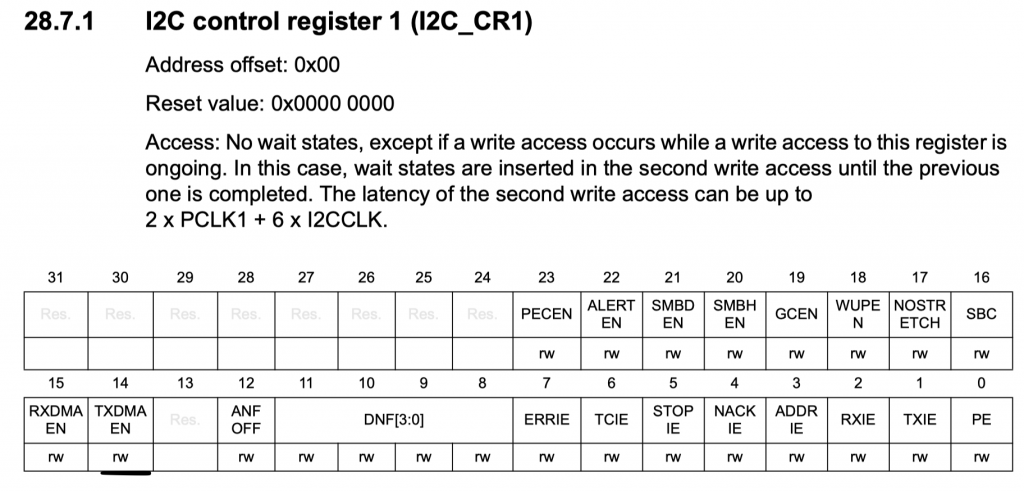
/*Enable DMA_TX*/
		I2C1->CR1|=I2C_CR1_TXDMAEN;
Then the following:
- Set the slave address.
- Set the address to be 7-bit mode.
- Length of the data.
- Mode to be write mode.
- Enable Auto end.
/*Set slave address*/
		I2C1->CR2=(slav_add<<1);
		/*7-bit addressing*/
		I2C1->CR2&=~I2C_CR2_ADD10;
		/*Set number to transfer to length for write operation*/
		I2C1->CR2|=(length<<I2C_CR2_NBYTES_Pos);
		/*Set the mode to write mode*/
		I2C1->CR2&=~I2C_CR2_RD_WRN;
		/*hardware end*/
		I2C1->CR2|=I2C_CR2_AUTOEND;
Now, for the DMA:
Disable the channel and wait until the channel is disabled:
		DMA1_Channel6->CCR&=~DMA_CCR_EN;
		while(DMA1_Channel6->CCR &DMA_CCR_EN);
Set the length:
DMA1_Channel6->CNDTR=length;
Set the memory address to be the buffer:
DMA1_Channel6->CMAR=(uint32_t)data;
Enable the DMA channel:
DMA1_Channel6->CCR|=DMA_CCR_EN;
Generate the start:
/*Generate start*/
I2C1->CR2|=I2C_CR2_START;
Wait until the tx_done is set to 1 and reset it after that:
while(tx_done==0);
tx_done=0;
For the interrupt handler of the DMA:
void DMA1_Channel4_7_IRQHandler(void)
	{

	if(DMA1->ISR & DMA_ISR_TCIF6)
		{
		tx_done=1;
		DMA1->IFCR=DMA_IFCR_CTCIF6;
		}
	}
Hence, the i2c_write_dma function is as following:
void i2c_write_dma(uint8_t slav_add, uint8_t *data, uint16_t length)
	{
	/*Enable I2C*/
		I2C1->CR1 |=I2C_CR1_PE;
		/*Enable DMA_TX*/
		I2C1->CR1|=I2C_CR1_TXDMAEN;
		/*Set slave address*/
		I2C1->CR2=(slav_add<<1);
		/*7-bit addressing*/
		I2C1->CR2&=~I2C_CR2_ADD10;
		/*Set number to transfer to length for write operation*/
		I2C1->CR2|=(length<<I2C_CR2_NBYTES_Pos);
		/*Set the mode to write mode*/
		I2C1->CR2&=~I2C_CR2_RD_WRN;
		/*hardware end*/
		I2C1->CR2|=I2C_CR2_AUTOEND;

		DMA1_Channel6->CCR&=~DMA_CCR_EN;
		while(DMA1_Channel6->CCR &DMA_CCR_EN);
		DMA1_Channel6->CNDTR=length;
		DMA1_Channel6->CMAR=(uint32_t)data;
		DMA1_Channel6->CCR|=DMA_CCR_EN;
		/*Generate start*/
		I2C1->CR2|=I2C_CR2_START;

		d
		//I2C1->CR1 &=~I2C_CR1_PE;
	}
3. Code:
For testing purposes, we shall use DS3231 and inside the main.c:
#include "i2c.h"
#include "uart.h"
#include "stdio.h"
#include "stdlib.h"
#define slave_add (0x68)


uint8_t data_rec[3],data_send[4];

int bcd_to_decimal(unsigned char x) {
    return x - 6 * (x >> 4);
}

int main()
	{
	uart_init();
	i2c_init(0x00708);
	while(1)
		{
		i2_read(slave_add,0x00,data_rec,3);
			for (volatile int i=0;i<3;i++)
				{
					data_rec[i]=bcd_to_decimal(data_rec[i]);
				}
			if(data_rec[0]!=0){
				if(data_rec[0]%5==0){
						data_send[0]=0x00;
						data_send[1]=0x00;
						data_send[2]=(rand() % 5);
						data_send[3]=(rand() % 5);
						i2c_write_dma(slave_add,data_send,4);
						}}
			printf("rtc data %d %d %d\r\n",data_rec[2],data_rec[1],data_rec[0]);
			for (int i=0;i<10000;i++);

		}

	}
You may download the code from here:
4. Demo:
Open serial terminal and set the buadrate to be 9600 and you should get this:
Happy coding 🙂
Add Comment