
In the previous guide (here), we saw how to configure timer to work in encoder mode. In this guide, we shall take it step further and measure the rotational speed in RPM (Revolutions per Minutes).
In this guide, we shall cover the following:
- How to measure RPM.
- Proposed experiment.
- Firmware development.
- Code.
- Demo.
1. How to Measure RPM:
Since the encoder is used to measure the RPM, the timer will overflow at each full rotation. Hence we can use interrupt to measure the timer between each full rotation in milliseconds.
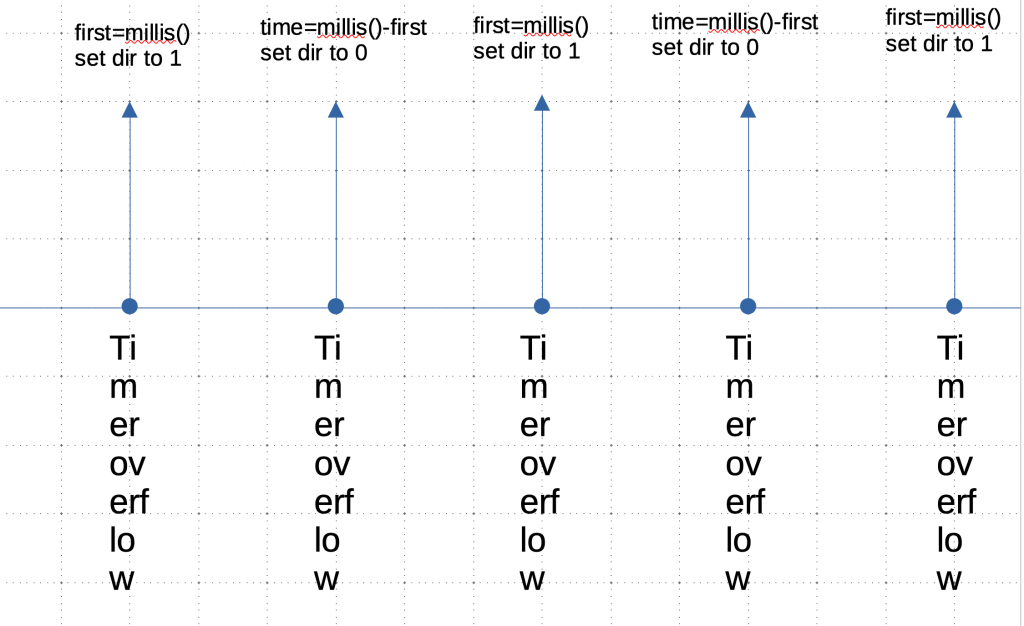
Since the timer will count up to the number of PPR provided by the encoder, an interrupt is generated. When the interrupt is generated, the time difference in milliseconds between each interrupt is measured and the the rptational speed in RPM is determined as following:
First, measure the time difference in seconds as following:

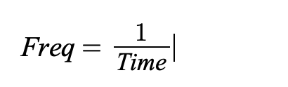
Then determine the frequency in Hz as following:
Then determine the RPM by multiplying the frequency by 60:

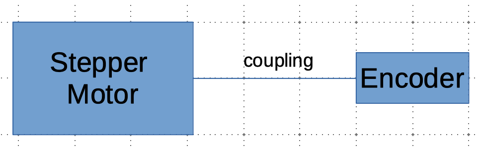
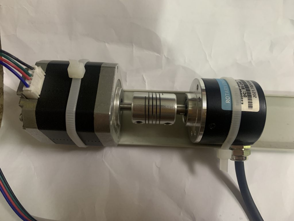
2. Proposed Experiment:
In order to test the code, a crude is conducted which includes the following components:
- Stepper Motor NEMA17 (42HD2037)
- Industrial Rotary encoder (LPD3806-360BM-G5-24C)
- Coupling (6mm-6mm)
3. Firmware development:
Since the timer in encoder is already discussed, we shall implement it here differently, we shall use timer3 and pins PB4 and PB5 as inputs for the timer
Hence the initializing the encoder mode as following:
void Encoder_init(uint16_t max_count)
	{
	RCC->APB1ENR|=RCC_APB1ENR_TIM3EN;
	RCC->AHB1ENR|=RCC_AHB1ENR_GPIOBEN;

	/*GPIO B configuration for timer mode */
	GPIOB->MODER|=GPIO_MODER_MODE4_1|GPIO_MODER_MODE5_1;
	GPIOB->MODER&=~(GPIO_MODER_MODE4_0|GPIO_MODER_MODE5_0);
	GPIOB->AFR[0]|=(AF02<<16)|(AF02<<20);

	/*Timer configuration for encoder mode */
	TIM3->ARR = max_count; //set the max count
	/*Timer in encoder mode*/
	TIM3->CCMR1 |= (TIM_CCMR1_CC1S_0 | TIM_CCMR1_CC2S_0 );
	TIM3->CCER &= ~(TIM_CCER_CC1P | TIM_CCER_CC2P);
	TIM3->SMCR |= TIM_SMCR_SMS_0 | TIM_SMCR_SMS_1;
	/*Enable interrupt*/
	TIM3->DIER|=TIM_DIER_UIE;
	NVIC_EnableIRQ(TIM3_IRQn);
	/*Start the timer */
	TIM3->CR1|=TIM_CR1_CEN;

	}
The interrupt handler as following:
void TIM3_IRQHandler(void)
	{

	if(TIM_SR_UIF&&TIM3->SR)
		{
		if(dir==1)
			{
			time=millis()-first;
			dir=0;
			}
		else {
			first =millis();
			dir=1;
			}

		TIM3->SR&=~TIM_SR_UIF;
		}
	}
For measuring RPM function:
float get_rpm()
	{
	time=(time/1000); /*from microseconds to seconds*/
	if(0==time)return 0;
	frequency=1/time;
	return frequency*60;
	}
If the time difference is zero, we shall return 0 indicating that the RPM is zero or beyond the capability of the current implantation.
Global variable:
#include "stm32f4xx.h"
#include "stdint.h"
#include "RPM_Encoder.h"
#include "delay.h"
const int AF02=0x02;
volatile uint64_t first, second, dir;
float frequency;
float time;
The header file:
#ifndef RPM_ENCODER_H_
#define RPM_ENCODER_H_

void Encoder_init(uint16_t max_count);
float get_rpm();
Since the code requires millis function, systick timer is used to generate interrupt each 1 milliseconds and delay as well as the following:
#include "delay.h"
#include "stm32f4xx.h"                  // Device header


volatile uint64_t ms,rms;
void systick_init_ms(uint32_t freq)
	{
	__disable_irq();
	SysTick->LOAD=(freq/1000)-1;
	SysTick->VAL=0;
	SysTick->CTRL=7; //0b00000111;
	NVIC_SetPriority(SysTick_IRQn,7);
	__enable_irq();
}

uint64_t millis(void)
	{
	__disable_irq();
	rms=ms; //store current ms in rms
	__enable_irq();
	return rms;
	}

void SysTick_Handler(void){
ms++;
}

void delay(uint32_t delay)
	{

		uint64_t start=millis();
	do
		{}while(millis()-start!=delay);
	}
The header:
#ifndef __delay__H__
#define __delay__H__


#include <stdint.h>
uint64_t millis(void);
void systick_init_ms(uint32_t freq);
void delay(uint32_t delay);
#endif
For the lcd screen, i2c based one is used and you can get the code from here.
For the stepper motor, please refer to the following topic.
4. Code:
You may download the code from here:
5. Demo:
Happy coding 🙂
Add Comment