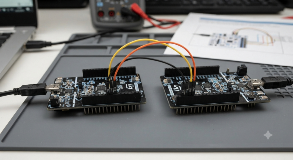
UART-based sensor emulation on an STM32F4 provides a cost-effective and highly controlled method to validate data processing algorithms and communication protocols without requiring the actual physical sensor hardware. This approach is essential for accelerating the development lifecycle by allowing engineers to simulate various environmental conditions, edge cases, and failure modes in a repeatable, deterministic software environment.
In this guide, we shall cover the following:
- Introduction.
- STM32CubeMX configuration.
- Hardware connection.
- Importing the project to STM32CubeIDE.
1. Introduction:
In the realm of embedded systems development, the integration of physical sensors often introduces a significant bottleneck. Developers frequently find themselves waiting for hardware arrival, troubleshooting intermittent signal noise, or struggling to create repeatable environmental conditions required to trigger specific edge-case logic. UART-based sensor emulation serves as a powerful architectural solution to these challenges, involving the use of a secondary microcontroller—in this case, an STM32F4 Nucleo-64—to mimic the data stream and behavioral characteristics of a target peripheral. By acting as a “software-defined sensor,” the emulator can stream pre-recorded or algorithmically generated data to a primary target device, creating a controlled, deterministic testing environment that mirrors real-world communication protocols.
Why Sensor Emulation is Necessary
Sensor emulation is necessary because it decouples software development from hardware availability and physical limitations. In complex systems, such as flight controllers or autonomous platforms, debugging sensor-fusion algorithms with raw physical data is inherently difficult because the physical world is rarely perfectly repeatable. Emulation allows engineers to:
- Accelerate Prototyping: Development begins immediately without waiting for custom PCBs or external components.
- Isolate Variables: You can inject “perfect” data to verify code, then introduce controlled errors (e.g., CRC errors, signal drift, or packet loss) to test the robustness of your error-handling routines.
- Safety and Cost: It is safer and significantly cheaper to test how a system reacts to “critical failure” readings when the sensor is merely an emulator rather than a physical part that might break or trigger real-world machinery.
Advantages and Disadvantages of Sensor Emulation
Understanding the trade-offs is crucial for determining if this approach fits your specific development cycle.
Advantages
- Deterministic Testing: Unlike physical sensors which are susceptible to ambient noise and physical interference, an emulator provides identical datasets every time the code runs. This is vital for regression testing.
- Protocol Flexibility: The emulator can be programmed to simulate various sensors on the same pins simply by changing the firmware, reducing the need to swap physical hardware modules during development.
- Accessibility to Rare Scenarios: Simulating “impossible” or rare events, such as a sensor overheating or failing during a specific transmission phase, is straightforward in software but nearly impossible to replicate reliably in the physical world.
Disadvantages
- Potential for Over-Simplification: An emulator may perfectly mimic a datasheet’s output but fail to replicate the subtle physical noise characteristics or non-linearities of a real component, potentially hiding bugs that only appear in hardware.
- Development Overhead: Building an emulator requires extra firmware development time and an additional MCU, which might not be justifiable for projects with very simple, off-the-shelf sensors.
- Timing Latency: Because the data is being serialized and sent over a UART line between two MCUs, there may be small overheads or jitter that do not exist if the sensor were directly connected to the target’s local bus.
2. STM32CubeMX Configuration:
Please note that Master and emulated sensor has the same configuration expect the emulated sensor will omit USART2.
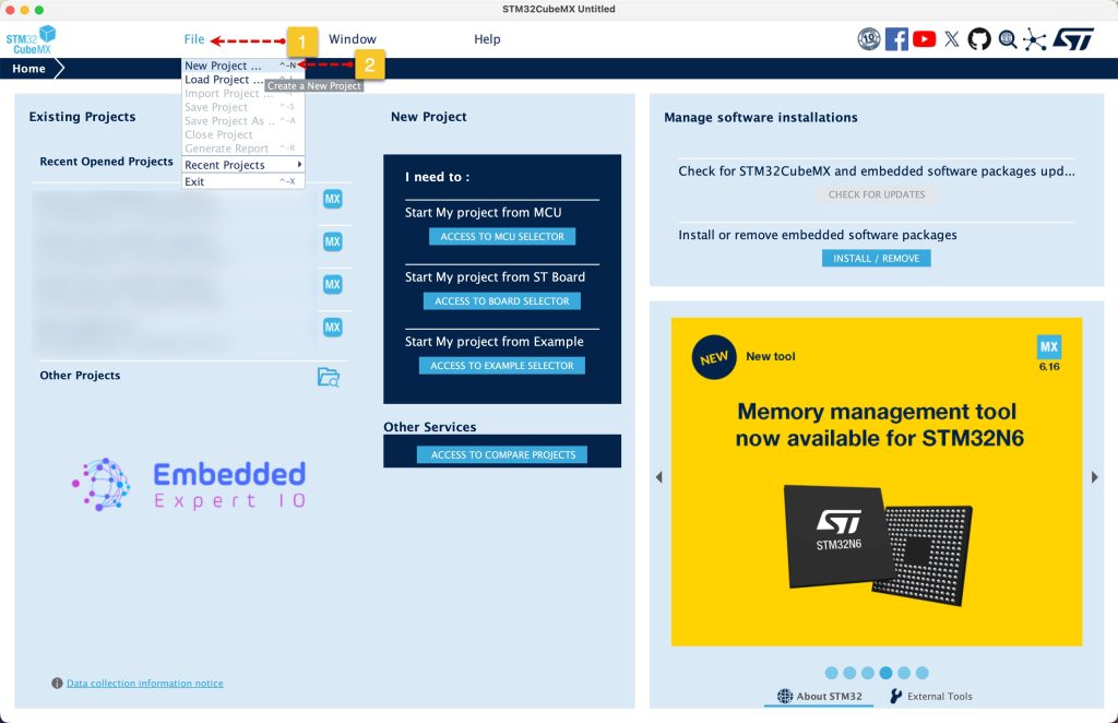
Open STM32CubeMX as start a new project as follows:
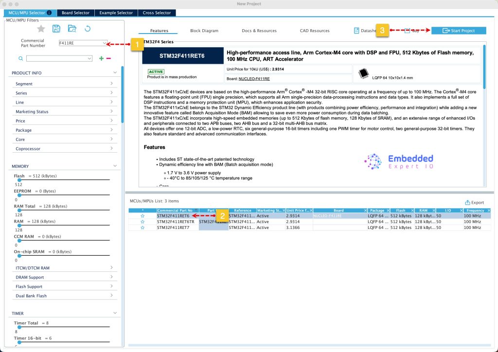
Search for your STM32 MCU, select the MCU and click on Start New Project as follows:
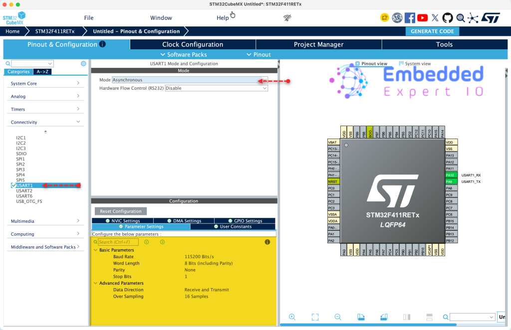
We shall use USART1 to communicate with the emulated sensor while USART2 to be used to print to the terminal.
From STM32CubeMX configuration, from communication, select USART1 and enable it in Asynchronous mode and keep the configuration as follows:
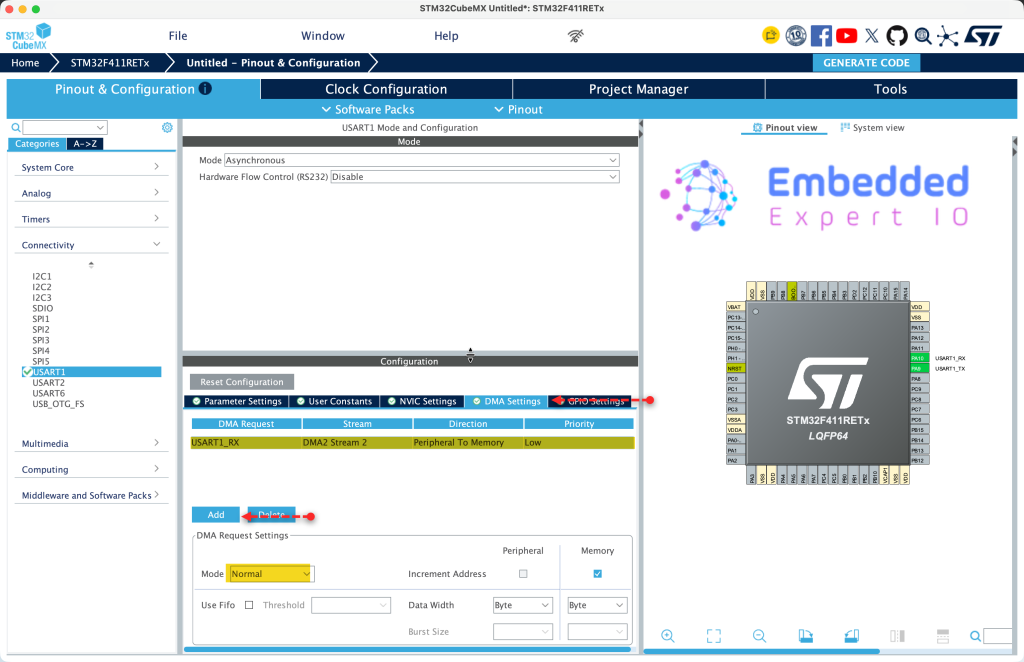
Next, from DMA tab, enable DMA for USART1_RX and configure the DMA as follows:
- Mode to normal.
- Data width to Byte.
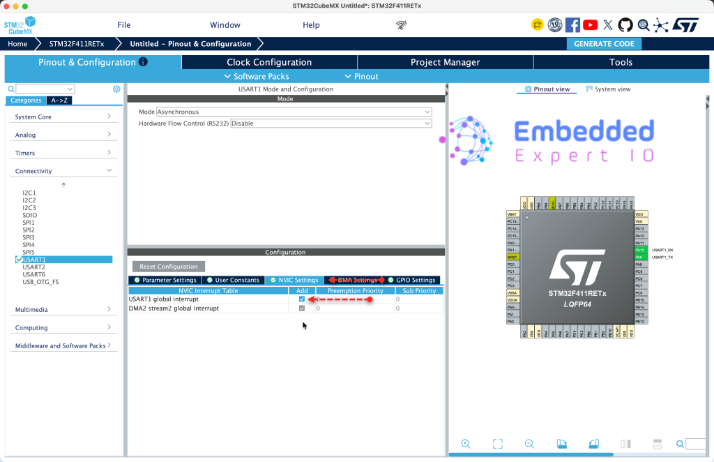
Next, from NIVC settings of USART1, enable USART1 global interrupt as follows:
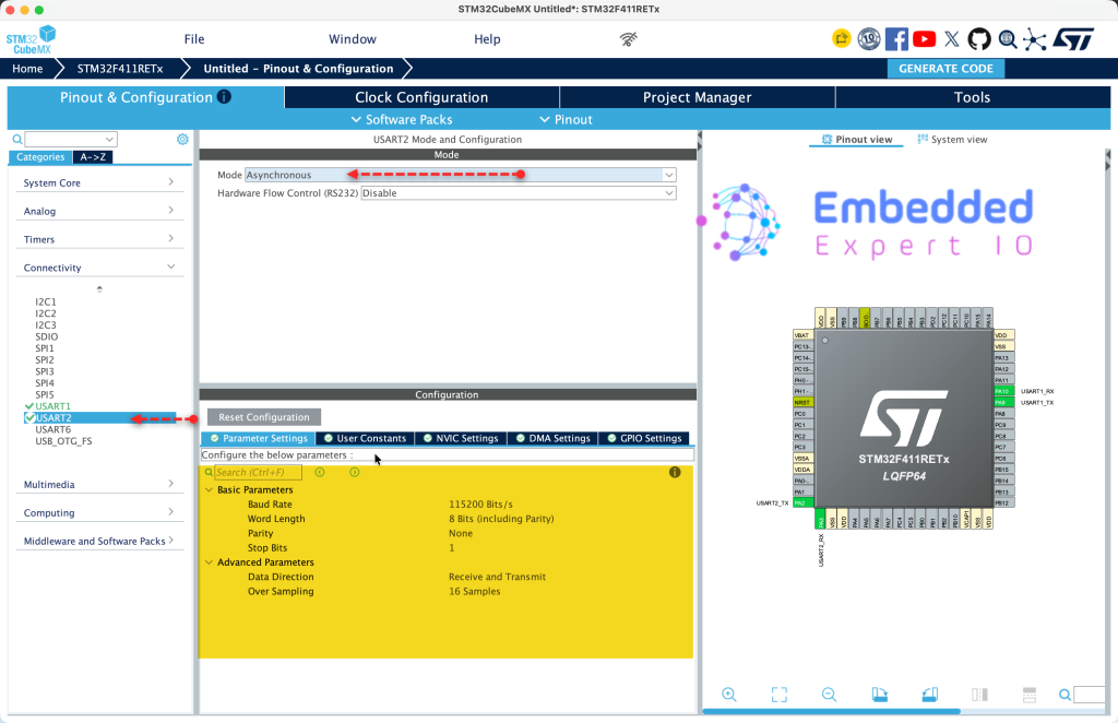
Next, we shall enable USART2 to print text to terminal (For main MCU only).
From communication, select USART2 and enable it in Asynchronous mode and keep the configuration as is as follows:
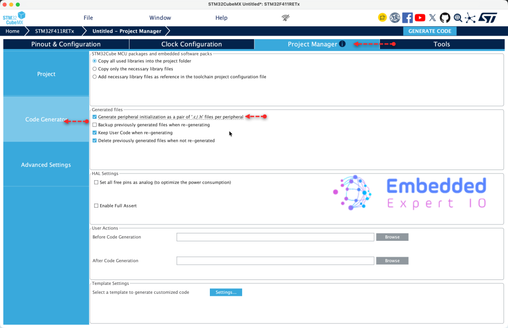
Next, from Project Manager tab, Code Generation, enable Generate peripheral initialization as pair .c/.h files per peripheral as follows:
Next, from Project tab, give the project a name, select toolchain/IDE to STM32CubeIDE and click on generate code as follows:
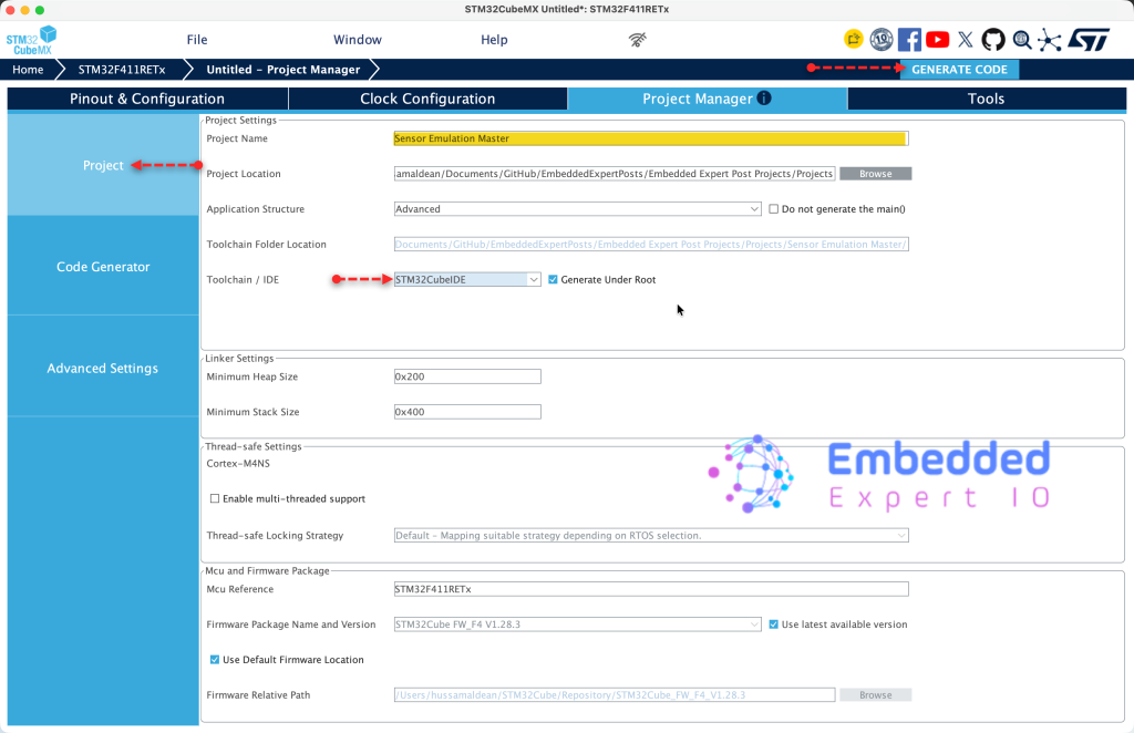
Thats all for STM32CubeMX.
3. Hardware Setup:
The setup as follows:
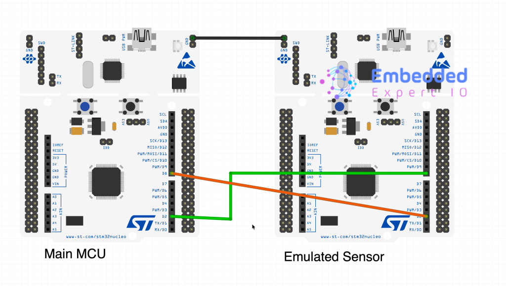
Connect TX of USART1 of main MCU to RX of USART1 of Emulated Sensor.
Connect RX of USART1 of main MCU to TX of USART1 of Emulated Sensor.
4. Importing the Project to SMT32CubeIDE:
pen STM32CubeIDE, select your workspace and click on Launch.
From the IDE, click File and select STM32 Project Create/Import as follows:
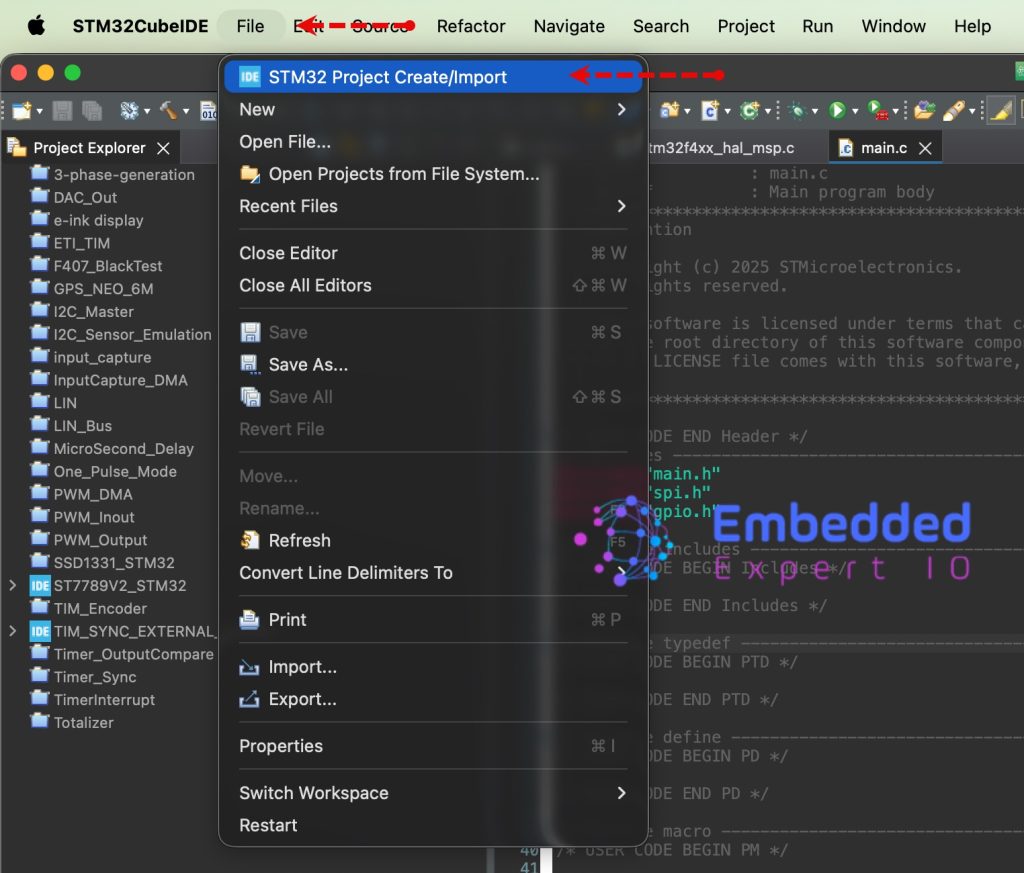
Next, from Import STM32 Project, select STM32CubeMX/STM32CubeIDE Project and click on Next as follows:
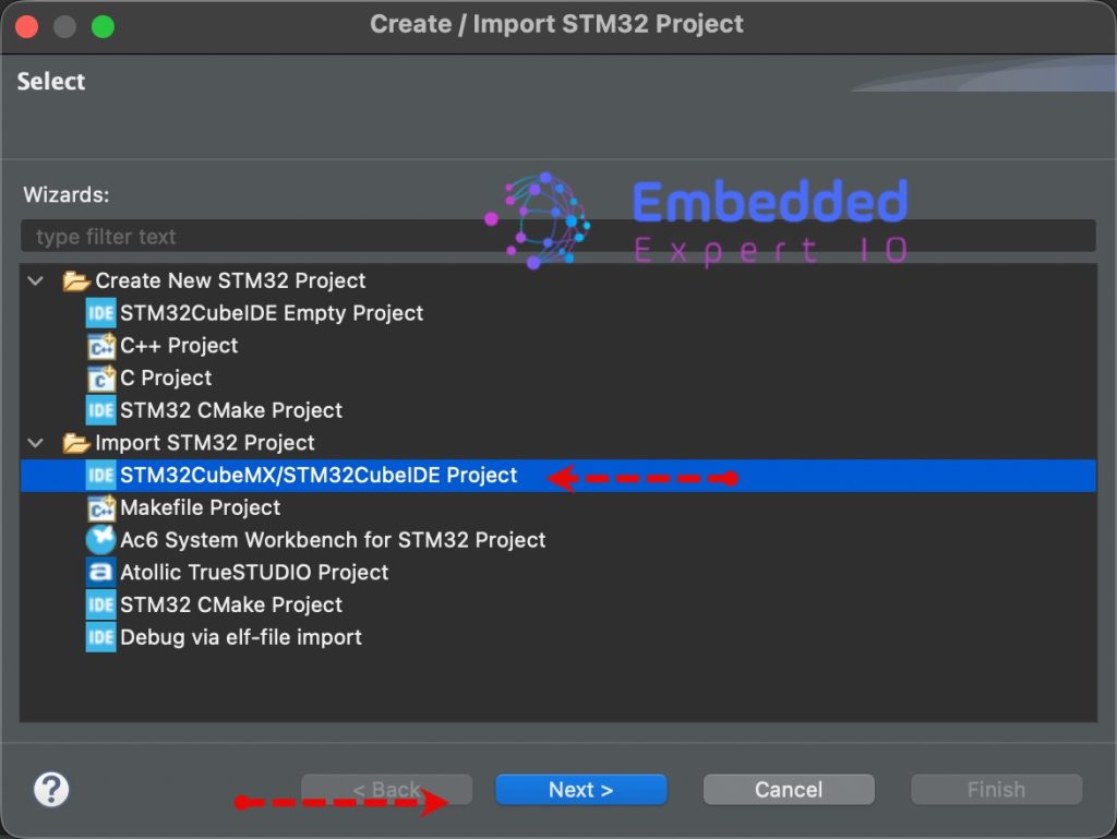
Next, select the folder that contains the .ioc file and click on Finish as follows:
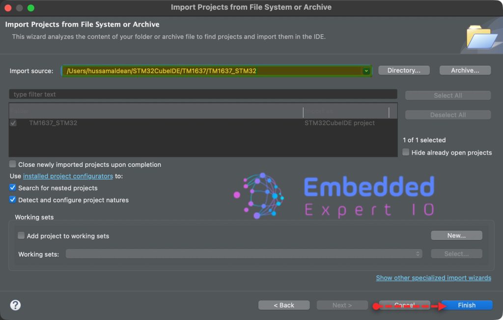
Note: Project name is for reference only.
Next part we shall start communicating between both before se start the emulation part.
Stay tuned.
Happy coding 😉

Add Comment