Break away from continuous polling loops by utilizing the STM32F4’s External Interrupt/Event Controller (EXTI) to capture asynchronous hardware events instantly. This guide demonstrates how to map a physical pin to an interrupt line using Low Layer (LL) drivers, allowing the microcontroller to execute a dedicated service routine the exact millisecond a button is pressed or a sensor changes state.
In this guide, we shall cover the following:
- Introduction.
- STM32CubeMX setup.
- Importing Project to STM32CubeIDE.
- Firmware development.
- Results.
1. Introduction:
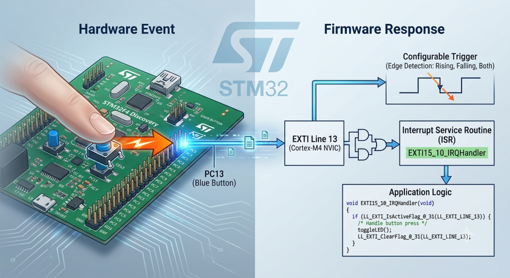
In embedded systems architecture, continuously checking the state of a pin in a while loop—known as polling—is highly inefficient. It consumes 100% of the CPU’s processing power and risks missing critical events if the microcontroller is busy executing another block of code. The External Interrupt/Event Controller (EXTI) solves this fundamental dilemma by shifting the responsibility from software monitoring to hardware detection.
By leveraging the STM32F4’s EXTI peripheral, you configure the silicon to watch specific pins autonomously. When a physical transition occurs (such as a voltage change from a button press), the hardware instantly pauses the main program execution, saves its current state, and jumps to a dedicated Interrupt Service Routine (ISR).
Core Mechanics of EXTI in Low Layer (LL)
Implementing EXTI via Low Layer drivers strips away the abstract callback wrappers found in HAL, exposing the true hardware pipeline. To capture an external event, three distinct layers must be bridged:
- System Configuration (SYSCFG): Microcontrollers pack hundreds of physical pins but have a limited number of internal interrupt channels. The SYSCFG peripheral acts as a multiplexer, mapping your specific physical pin (like PC13) to the corresponding internal interrupt line (EXTI Line 13).
- The EXTI Controller: This layer dictates how the hardware should react. Using LL functions, you can configure the edge detector to trip on a Rising Edge (voltage goes low-to-high), a Falling Edge (voltage goes high-to-low), or Both.
- The Nested Vectored Interrupt Controller (NVIC): Positioned inside the ARM Cortex-M4 core, the NVIC is the ultimate gatekeeper of all exceptions. It manages the execution priority of the interrupt, ensuring that time-critical hardware tasks take precedence over standard application logic.
By configuring these registers directly with LL, you ensure the absolute lowest possible latency between a physical finger pressing a button and your firmware executing a response. This guide will walk you through setting up this high-performance pipeline, paving the way for low-power sleep modes and ultra-responsive applications.
2. STM32CubeMX Configuration:
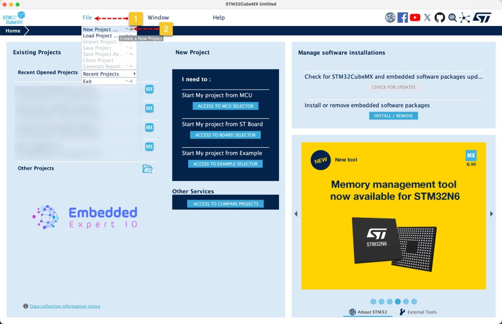
Open STM32CubeMX as start a new project as follows:
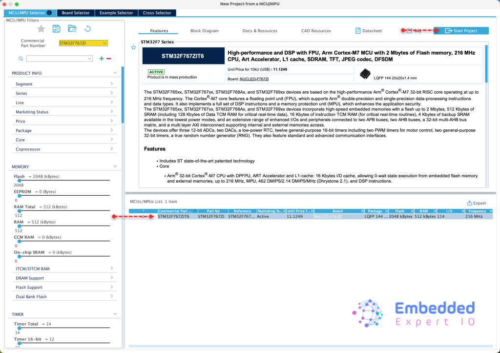
Search for your STM32 MCU, select the MCU and click on Start New Project as follows:
This guide shall use STM32F767Zi Nucleo-144 board
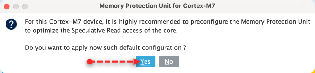
Since STM32F7 is an ARM Cortex M7, it requires to setup the cache, we shall go with the default setup since we don’t care about it right now.
Next, from user manual of Nucleo-144, we can find that the user button is connected to PC13 and LEDS as follows:
- LD1 is connected to PB0.
- LD2 is connected to PB7.
- LD3 is connected to PB14.

We shall use LD2 and LD3 for this guide.
Set PB7 and PB14 as output as follows:
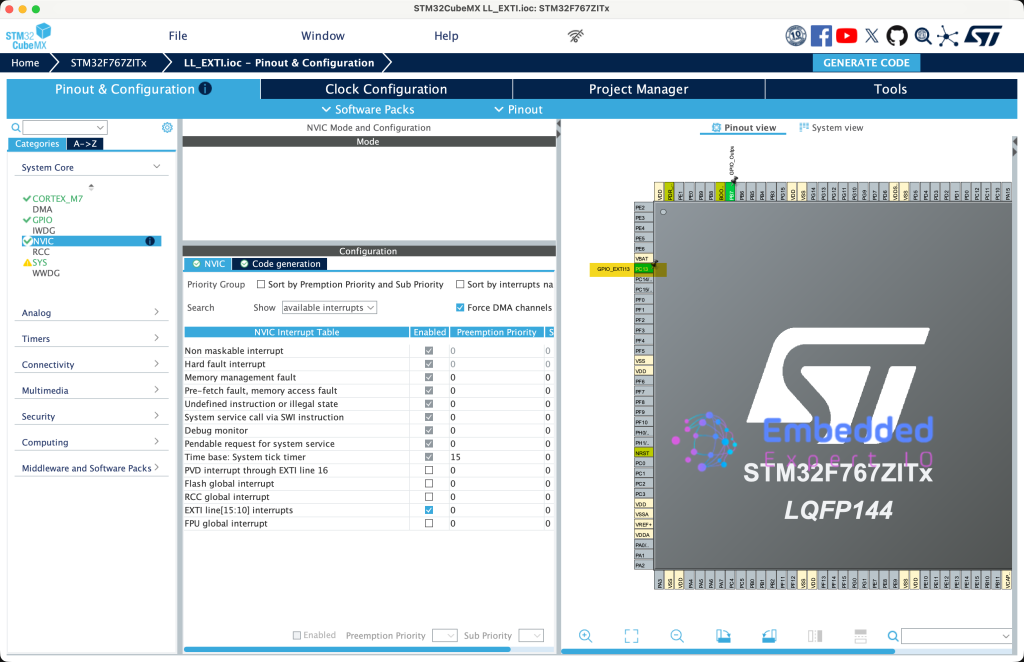
Next, set PC13 as EXTI line 13 as follows:
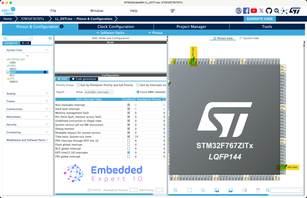
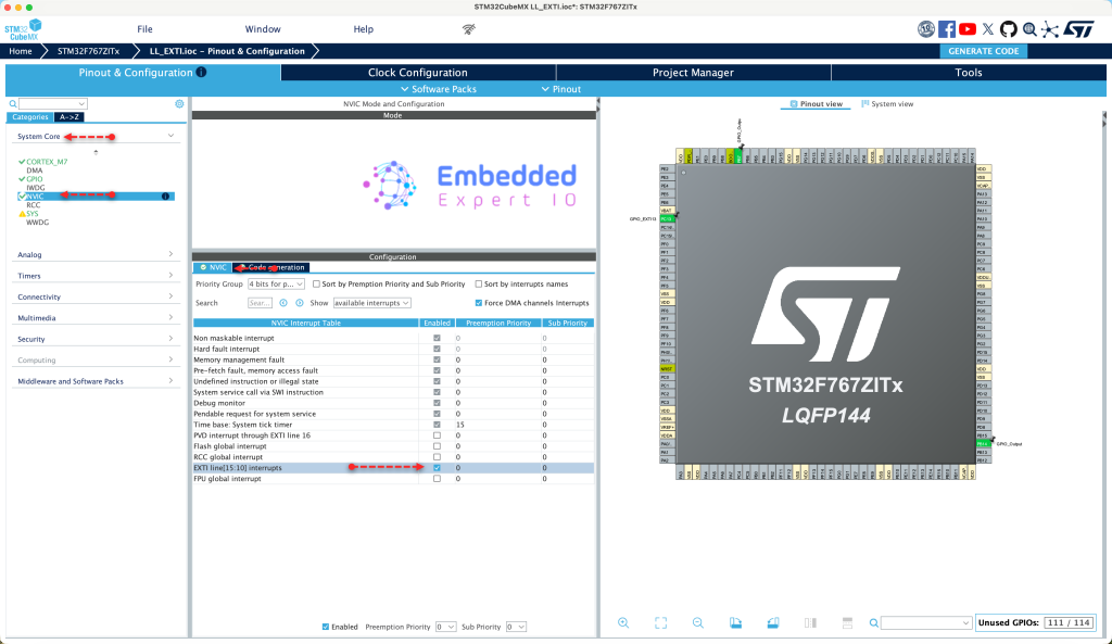
Next, from System Core, NVIC, enable EXTI line 13 from NVIC tab as follows:
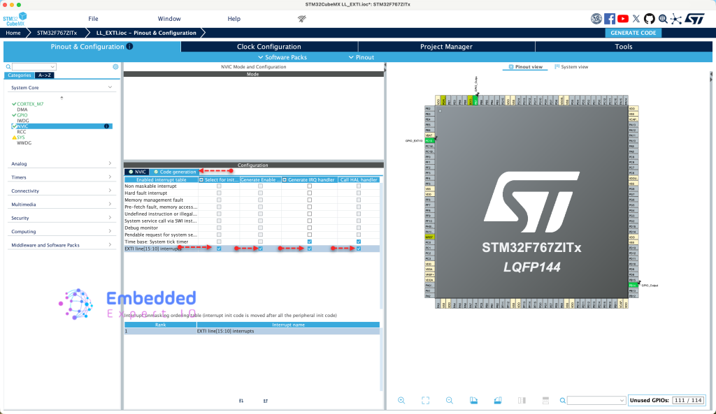
From Code Generation, enable code generation for the interrupt as follows:
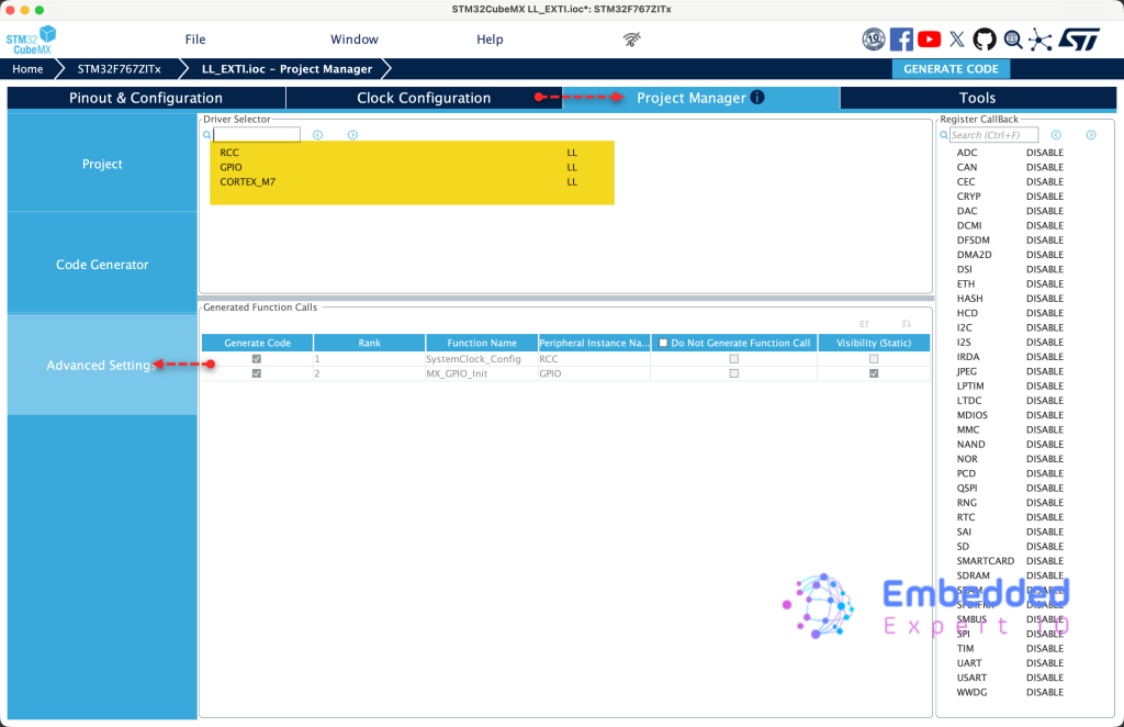
Next, from Project Manager tab, select advanced settings and enable LL for every peripheral as follows:
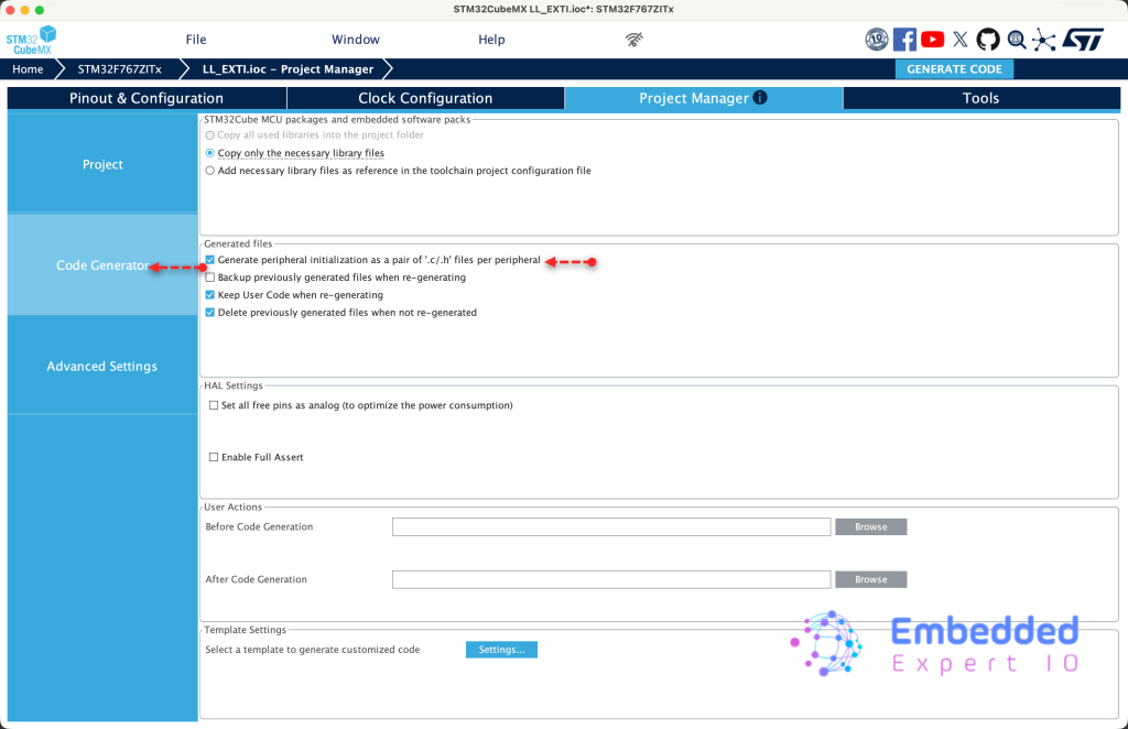
From Code Generation, enable Generate peripheral initialization as pair of .c/.h file as follows:
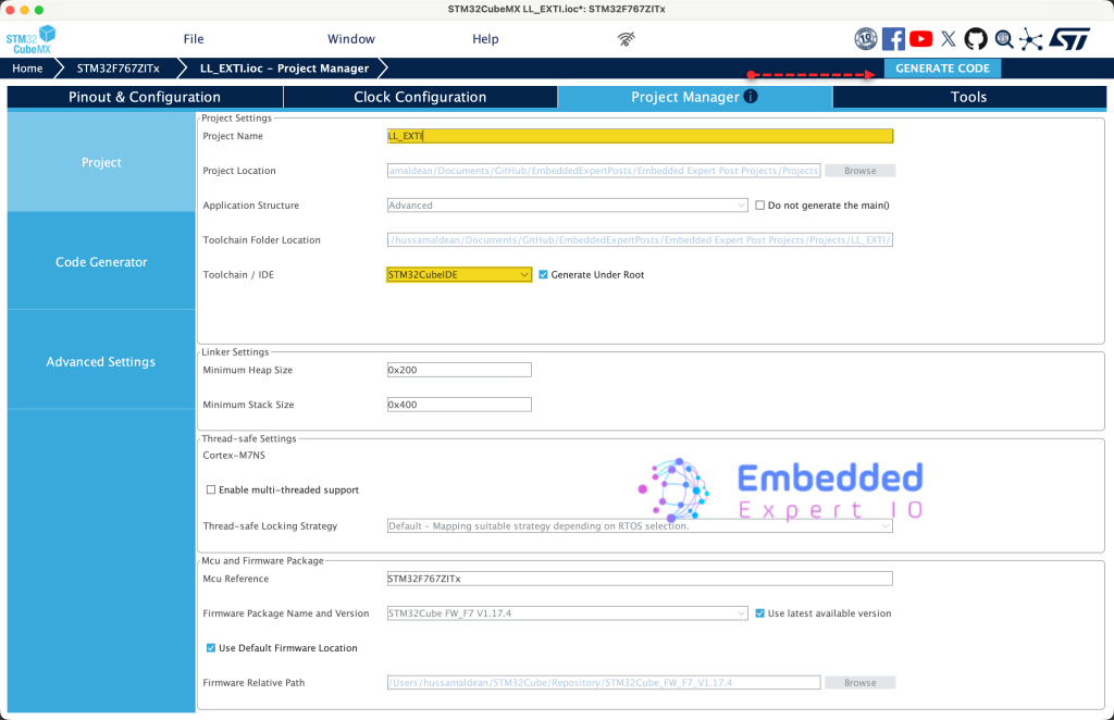
Finally, from Project tab, give the project a name and set Toolchain/IDE to STM32CubeIDE and click on generate code as follows:
Thats all for STM32CubeMX configuration.
3. Importing the Project to STM32CubeIDE:
Open STM32CubeIDE, select your workspace and click on Launch.
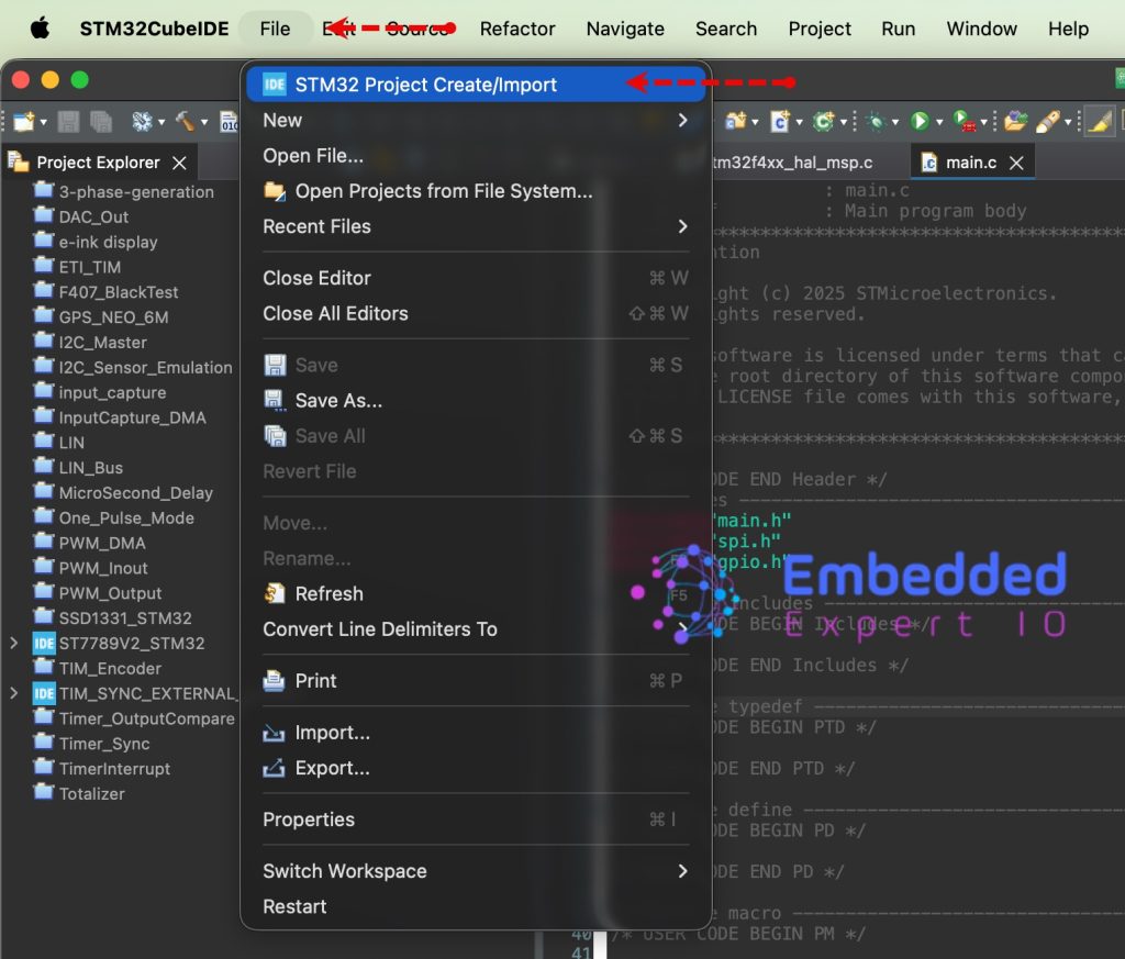
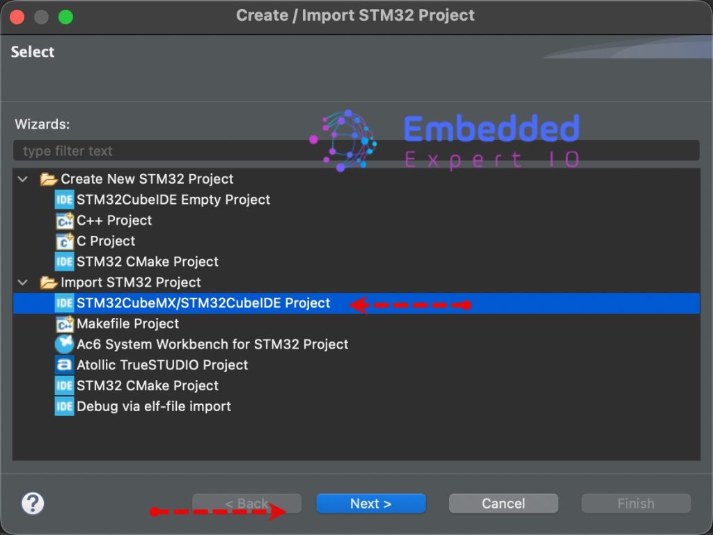
From the IDE, click File and select STM32 Project Create/Import as follows:
Next, from Import STM32 Project, select STM32CubeMX/STM32CubeIDE Project and click on Next as follows:
Next, select the folder that contains the .ioc file and click on Finish as follows:
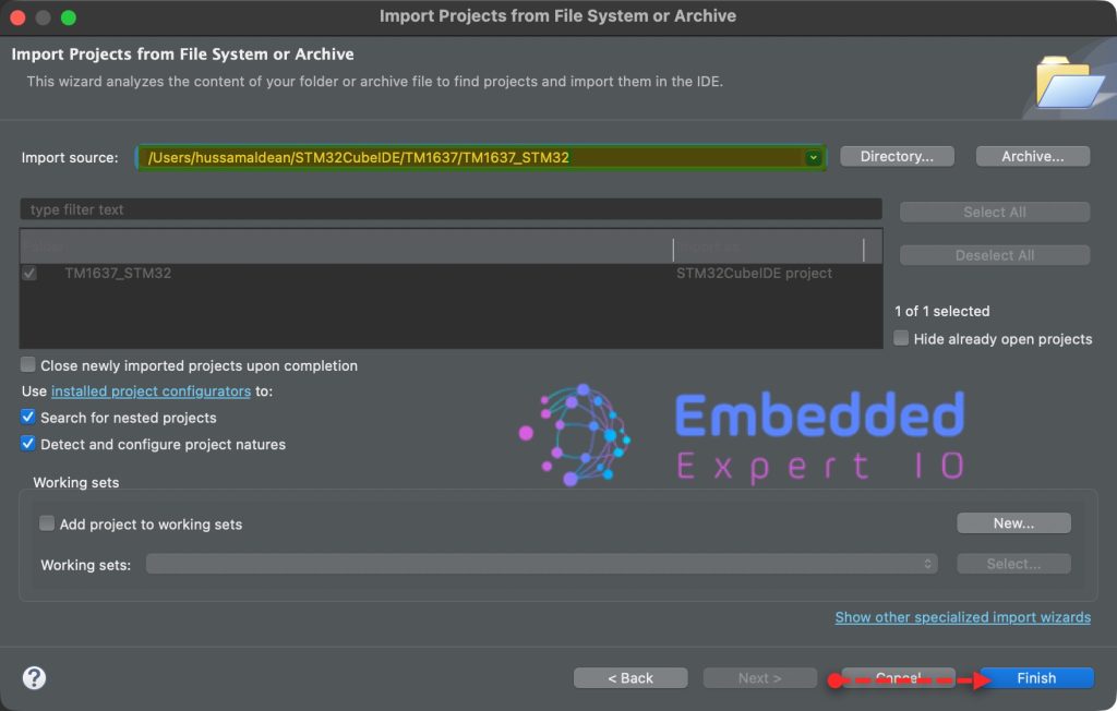
Note: Project name is for reference only.
4. Firmware Development:
First, we need to implement time base, for how to implement time base, please refer to this guide.
Next, in stm32f7xx_it.c source file, in user code begin external variables (EV), declare the following external variables:
extern volatile uint8_t exti_triggered;
extern volatile uint32_t currentTime;
Next, in void EXTI15_10_IRQHandler(void) function, in USER CODE BEGIN LL_EXTI_LINE_13, set exti_triggered to 1, capture the current ticks and store it in currentTime and set pin PB7 to high as follows:
 exti_triggered=1;
 currentTime=getCurrentTicks();
 LL_GPIO_SetOutputPin(GPIOB, LL_GPIO_PIN_7);
Next, in main.c source file.
In user code begin PV, declare the following variables:
volatile uint8_t exti_triggered;

volatile uint32_t currentTime;
Declare a macro that holds a period for LED to remains on as follows:
#define period 2000
The led shall be on for 2 seconds.
Next, in while 1 loop, in user code begin 3:
Check if the two seconds elapsed and exti is triggered, if the condition is true, turn off the led and reset the exti flag as follows:
if((getCurrentTicks()-currentTime>period)&&exti_triggered==1)
{
  LL_GPIO_ResetOutputPin(GPIOB, LL_GPIO_PIN_7);
  exti_triggered=0;

}
Next, toggle the LED connected to PB14 each 500ms as follows:
if(getCurrentTicks()%500==0)
{
  LL_GPIO_TogglePin(GPIOB, LL_GPIO_PIN_14);
}
Thats all for the firmware.
Save, build the project and run it as follows:

You may download the project from here.
5. Results:
You should get the following when you run the project on STM32F767Zi Nucleo-144:
Happy coding 😉
Add Comment