Mastering the BMP180 begins with establishing a robust communication bridge between the STM32 and your development environment. By prioritizing the configuration of UART and enabling floating-point formatting, you create a foundation for precise data logging and effective real-time debugging.
In this guide, we shall cover the following:
- Introduction.
- STM32CubeMX setup.
- Importing the project to STM32CubeIDE.
- Hardware connection.
- Minimal firmware setup.
1. Introduction:
The BMP180 is a high-precision, digital barometric pressure sensor that serves as a cornerstone for hobbyists and engineers transitioning from basic environmental monitoring to sophisticated navigational and meteorological projects. As the successor to the venerable BMP085, the BMP180 offers a significant leap in performance, providing a robust solution for measuring both atmospheric pressure and temperature via a standard $I^2C$ interface. This sensor is particularly favored for its low power consumption and high stability, making it ideal for mobile devices and remote battery-operated stations.
Key Features and Technical Specifications
The BMP180 is designed to operate in a variety of environments with a focus on accuracy and efficiency:
- Pressure Range: It can measure atmospheric pressure from 300 hPa to 1100 hPa, which corresponds to an altitude range of +9000m to -500m relative to sea level.
- Temperature Sensing: An integrated temperature sensor allows for internal compensation of the pressure readings, ensuring that data remains accurate despite fluctuating ambient conditions.
- Low Noise: In its “Ultra High Resolution” mode, the sensor can detect changes in altitude as small as 0.17 meters, making it sensitive enough for indoor floor-level detection.
- Efficiency: With a current consumption as low as 3 µA in standard mode, it is a leading choice for power-constrained applications.
- Communication: It utilizes the $I^2C$ protocol, allowing for simple two-wire integration with microcontrollers like the STM32F767ZI Nucleo-144, which features a high-performance ARM Cortex-M7 core capable of handling complex sensor fusion algorithms.
Diverse Applications
Beyond simple weather reporting, the data provided by the BMP180 enables a wide array of functional use cases:
- Altimetry and Navigation: Used extensively in drones and RC aircraft to maintain stable flight altitude and assist in GPS-based navigation.
- Weather Forecasting: By monitoring “pressure tendencies” (the rate of change in barometric pressure), developers can predict local weather shifts or incoming storm fronts.
- Indoor Positioning: Its high sensitivity allows for “Dead Reckoning” applications, helping devices determine which floor of a building a user is on when GPS signals are unavailable.
- Industrial Monitoring: Useful in HVAC systems for monitoring pressure drops across filters or within ducts to ensure optimal system performance.
Guide Overview: Part 1
In the first installment of this guide, we lay the groundwork for a professional development workflow. Before we can dive into the $I^2C$ registers and calibration coefficients, we must establish a reliable communication link between the hardware and our workstation. We will focus on:
- Environment Setup: Configuring the toolchain to ensure the high-performance STM32F7 series is ready for deployment.
- UART Configuration: Setting up Universal Asynchronous Receiver-Transmitter (UART) communication to act as our primary debugging window.
- Printf Retargeting and Float Support: Overcoming a common hurdle in embedded C by enabling
printfto output floating-point numbers. This is critical for the BMP180, as its raw data requires complex floating-point calculations to yield human-readable temperature and pressure values.
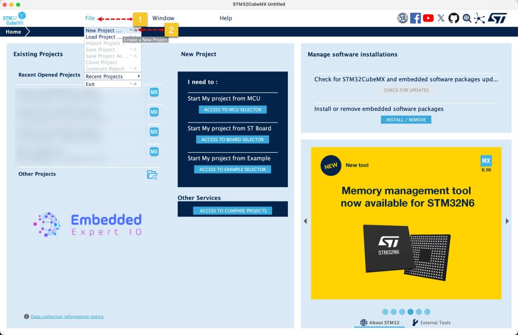
2. STM32CubeMX Setup:
Open STM32CubeMX as start a new project as follows:
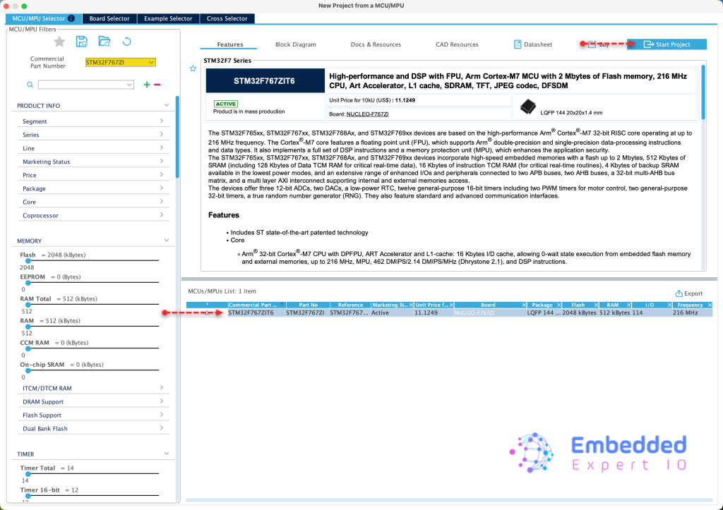
Search for your STM32 MCU, select the MCU and click on Start New Project as follows:
This guide shall use STM32F767Zi Nucleo-144 board
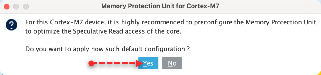
Since STM32F7 is an ARM Cortex M7, it requires to setup the cache, we shall go with the default setup since we don’t care about it right now.
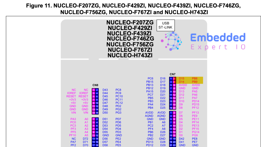
Next, from the user manual of Nucleo-144, we can find that D14 and D15 of Ardunio pins are SDA and SCL respectively. By referring to pinout, we can find that they are PB9 and PB8 respectively.
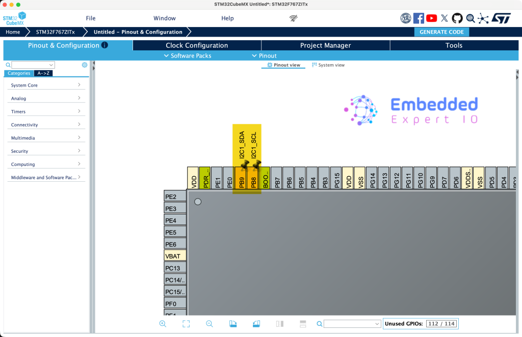
From STM32CubeMX, set PB8 and PB9 as I2C1_SCL and I2C1_SDA respectively as follows:
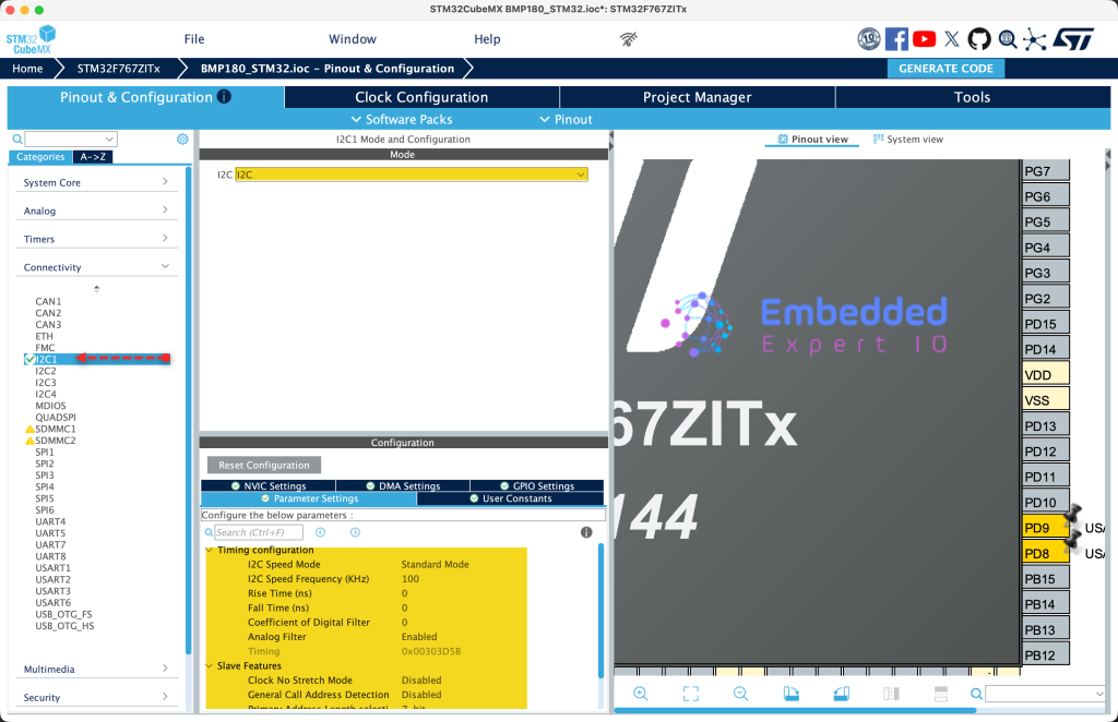
Next, from connectivity, enable I2C1 and keep the settings as default as follows:
Next, from the user manual of Nucleo-144, the UART communication, we can find that PD8 and PD9 are connected to USART3 TX and USART3 RX respectively.
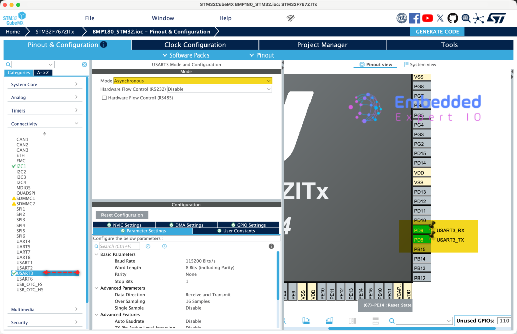
Hence, set these pins are PD8 and PD9 to USART3 TX and USART3 RX respectively. Once that has been done, from connectivity, enable USART3 as Asynchronous Mode as follows:
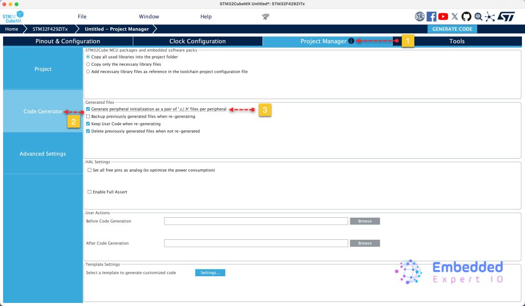
Next, from project tab, select code generation and enable generate peripherals initialization as pair of .c/.h files as follows:
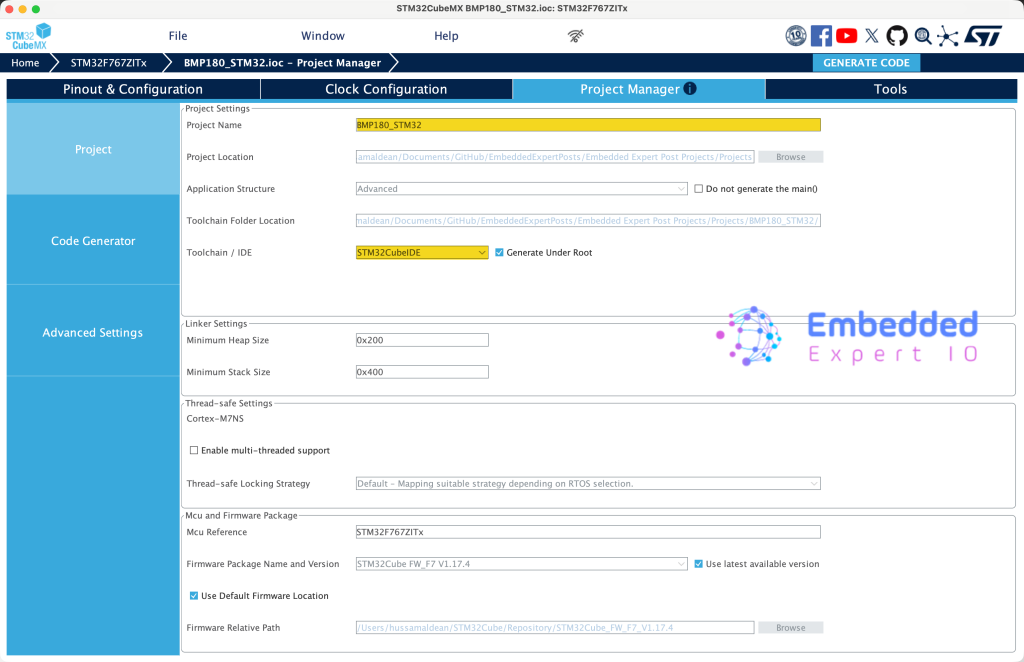
Finally from project, set the destination, give the project a name and set toolchain/IDE to STM32CubeIDE and click on Generate Code as follows:
Thats all for STM32CubeMX Configure.
3. Importing the Project to STM32CubeIDE:
Open STM32CubeIDE, select your workspace and click on Launch.
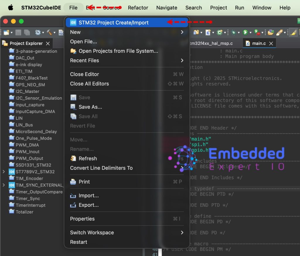
From the IDE, click File and select STM32 Project Create/Import as follows:
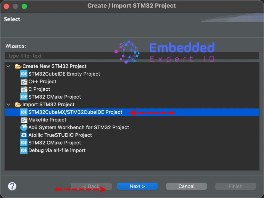
Next, from Import STM32 Project, select STM32CubeMX/STM32CubeIDE Project and click on Next as follows:
Next, select the folder that contains the .ioc file and click on Finish as follows:
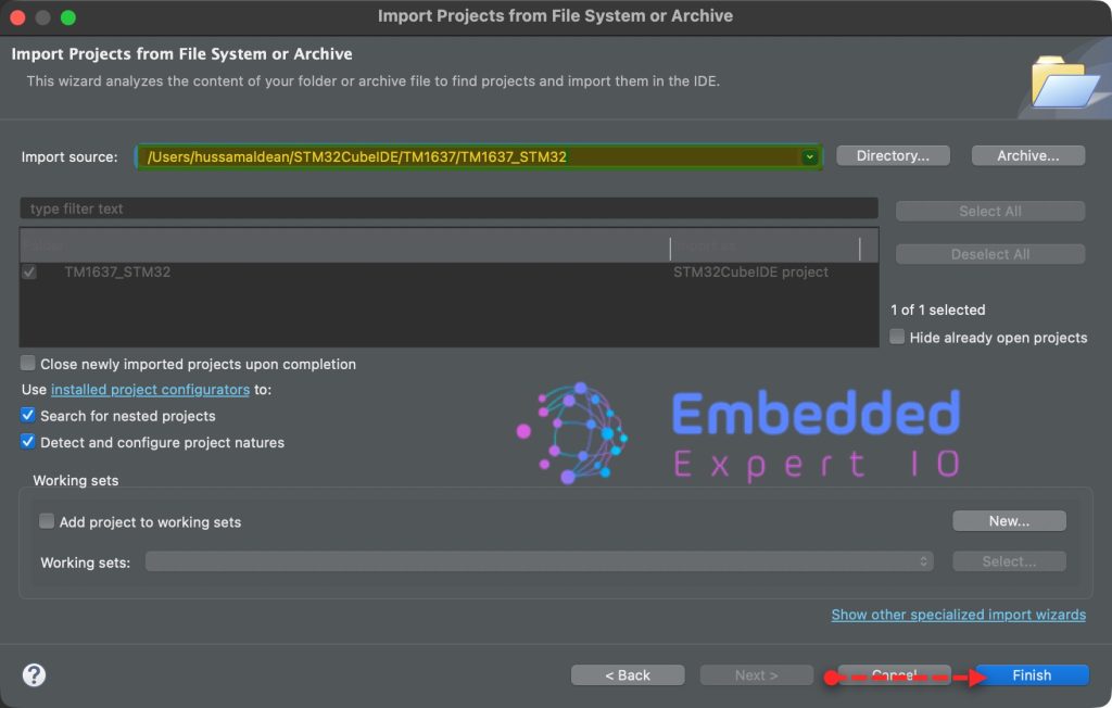
Note: Project name is for reference only.
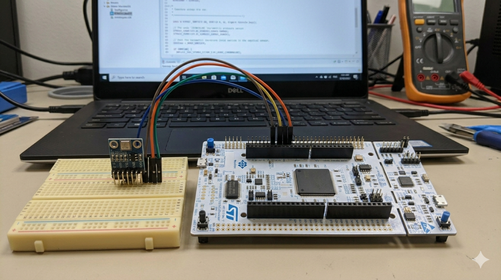
4. Hardware Connection:
The connection as follows:
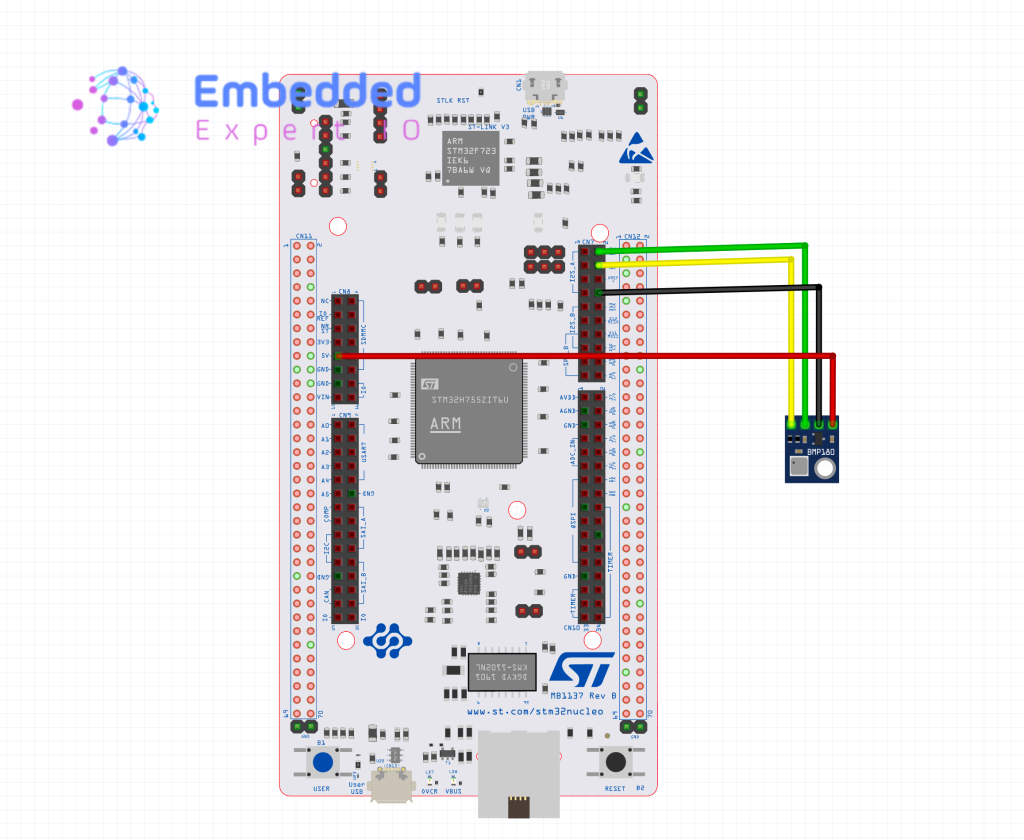
| BMP180 Module | STM32F767Zi Nucleo-144 |
| Vin | 5V |
| GND | GND |
| SCL | PB8 (D15) |
| SDA | PB9(D14) |
5. Minimal Firmware Setup:
In STM32CubeIDE, open uart.c file.
In user code begin 0, declare the following function:
int __io_putchar(int ch)

{
	HAL_UART_Transmit(&huart3, (uint8_t*)&ch, 1, 10);
	return ch;
}
This function shall redirect printf to use UART to send data.
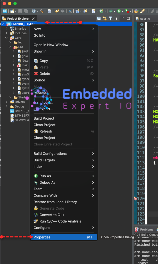
Next, from project explorer, right click on the project as follows:
Next, from C/C++, select MCU/MPU Settings, enable Use float with printf from newlib-nano and click on Apply and Close
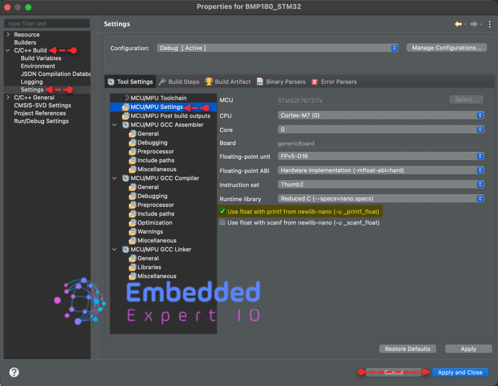
This will allow us to print float in printf.
To test the printf to print float values:
In main.c file, in user code begin includes, include stdio.h as follows:
#include "stdio.h"
Also, include math.h to handle some functions to test as follows:
#include "math.h"
Next, in user code begin 0, declare the following function:
float calcSin(float degree)
{
	float radian;
	radian=degree * (M_PI / 180.0);

	return sin(radian);
}
This function shall calculate the sin angle in degrees.
In user code begin 3 in while 1 loop:
for (int i=0;i<=180;i++)
	  {
		  printf("Sine Value of %d degree is %0.10f \r\n",i,calcSin(i));
		  HAL_Delay(10);
	  }
This will loop from 0 to 180 and print its value.
Thats all for the firmware.
Save, build the project and run it as follows:

6. Results:
Open serial terminal application and set the buadrate to 115200 and you should get the following:
In part 2, we shall go in details how to communicate with the sensor.
Stay tuned.
Happy coding 😉
Add Comment