
Transition from driving outputs to interpreting the physical world by configuring the STM32F4’s GPIO pins as digital inputs using Low Layer (LL) drivers. This guide covers how to read external signals with minimal latency, ensuring your firmware reacts instantly to button presses or sensor triggers.
In this guide, we shall cover the following:
- Introduction to input mode.
- STM32CubeMX setup.
- Import project to STM32CubeIDE.
- Firmware development.
- Results.
1. Introduction to Input Mode:
After mastering digital outputs, the next step in embedded development is learning how to listen to the environment. In this guide, we explore GPIO Input configuration using the Low Layer (LL) drivers, which allows your STM32F411 to detect external signals—such as button presses, sensor triggers, or switch toggles—with microsecond precision.
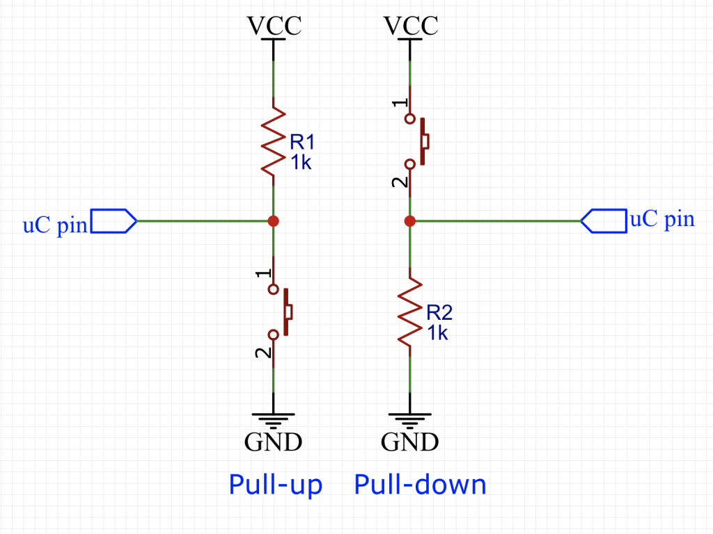
Understanding Pull-up and Pull-down Resistors
In digital electronics, an input pin should never be “floating.” If a pin isn’t connected to a steady voltage, it acts like an antenna, picking up electrical noise that causes the software to see random 1s and 0s. To prevent this, we use internal resistors to “tie” the pin to a known state.
- Pull-up Resistors: These connect the input pin to VDD (3.3V). By default, the microcontroller reads a Logic HIGH. When you press a button that connects the pin to Ground, the state “pulls” down to a Logic LOW.
- Pull-down Resistors: These connect the input pin to VSS (Ground). By default, the microcontroller reads a Logic LOW. When an external signal provides 3.3V, the state “pulls” up to a Logic HIGH.
2. STM32CubeMX Setup:
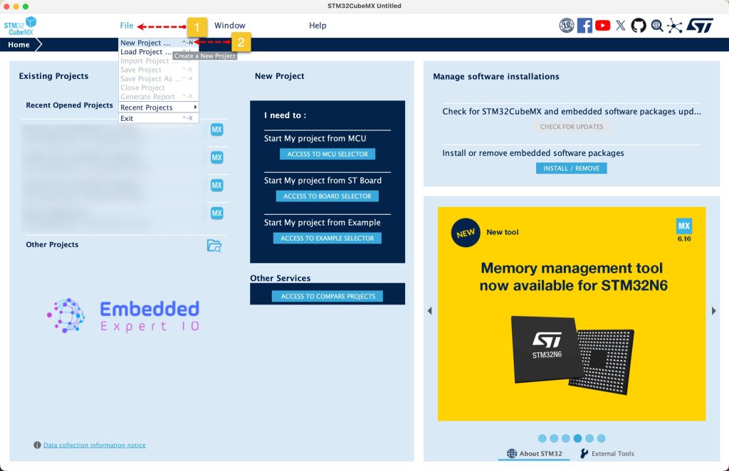
Open STM32CubeMX as start a new project as follows:
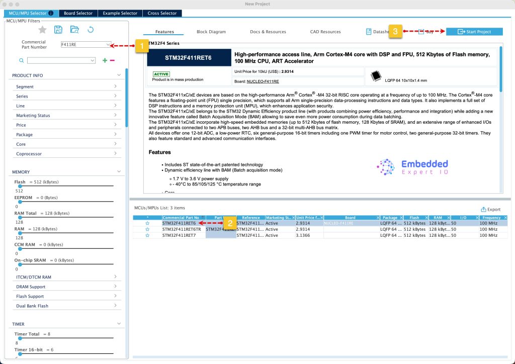
Search for your STM32 MCU, select the MCU and click on Start New Project as follows:
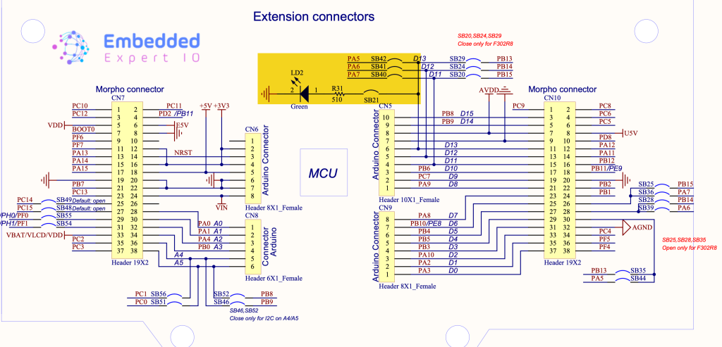
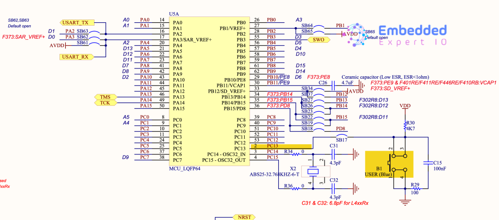
From the user manual of STM32F411 Nucleo-64, we can find that the LD2 is connected to PA5:
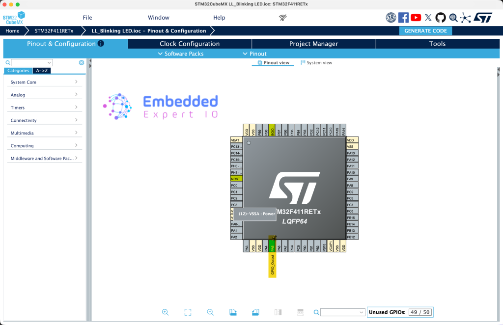
Next, set PA5 as output as follows:
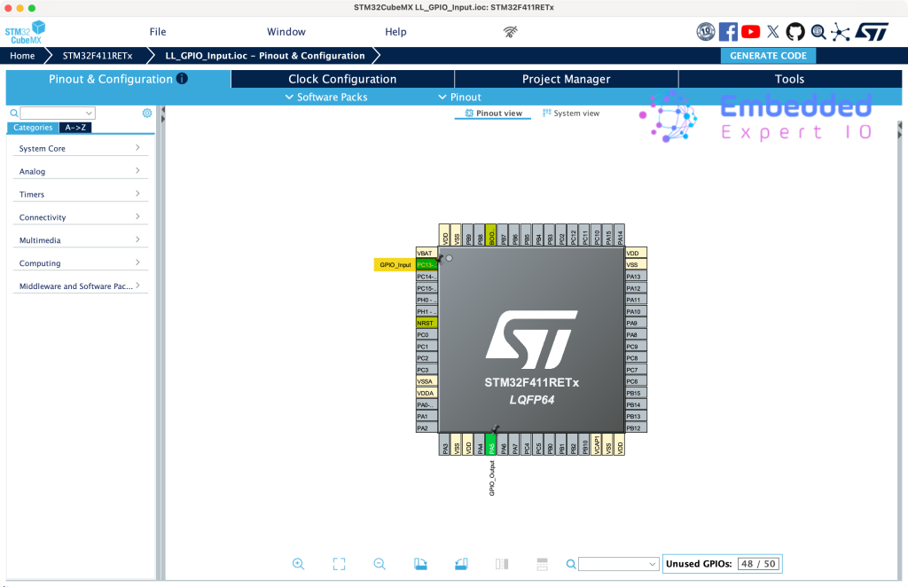
Next, from the user manual of STM32F411 Nucleo-64, we can find that the user button is connected to PC13 as follows:
Set PC13 as GPIO input as follows:
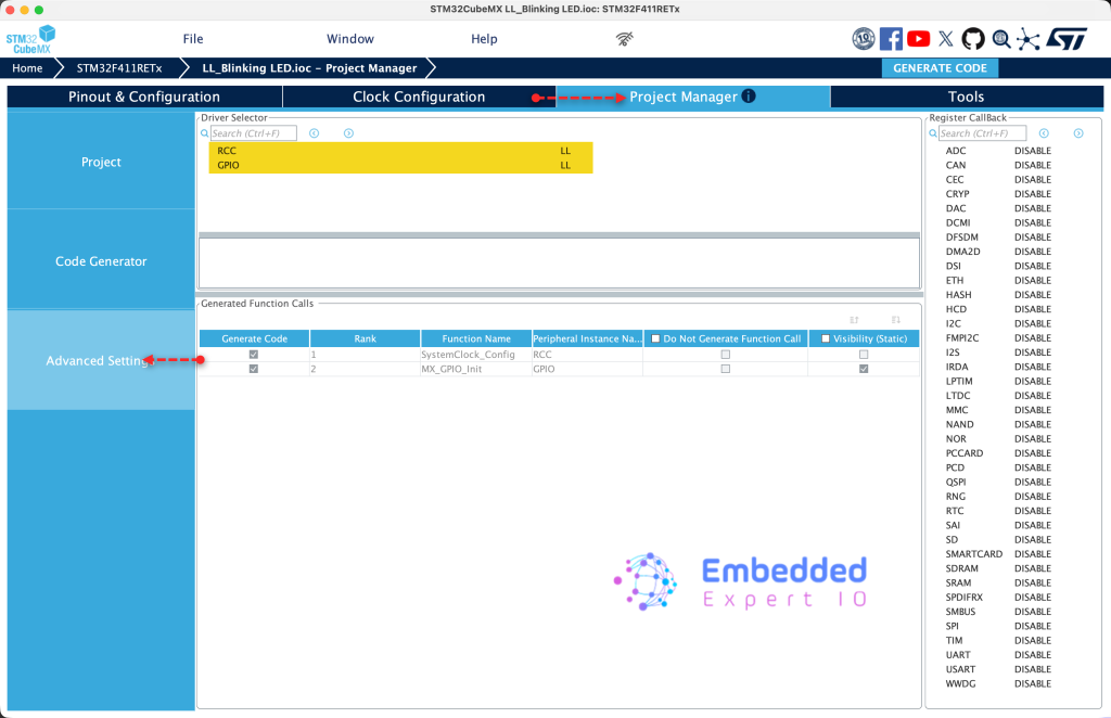
Next, from Project Manager, head to Advanced Settings, set both RCC and GPIO to LL as follows:
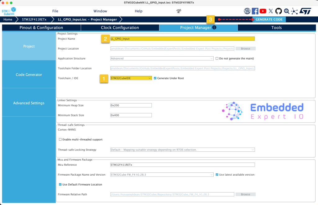
Next, from Project, give the project a name and set toolchain/IDE to STM32CubeIDE and click on Generate Code as follows:
3. Importing the Project to STM32CubeIDE:
Open STM32CubeIDE, select your workspace and click on Launch.
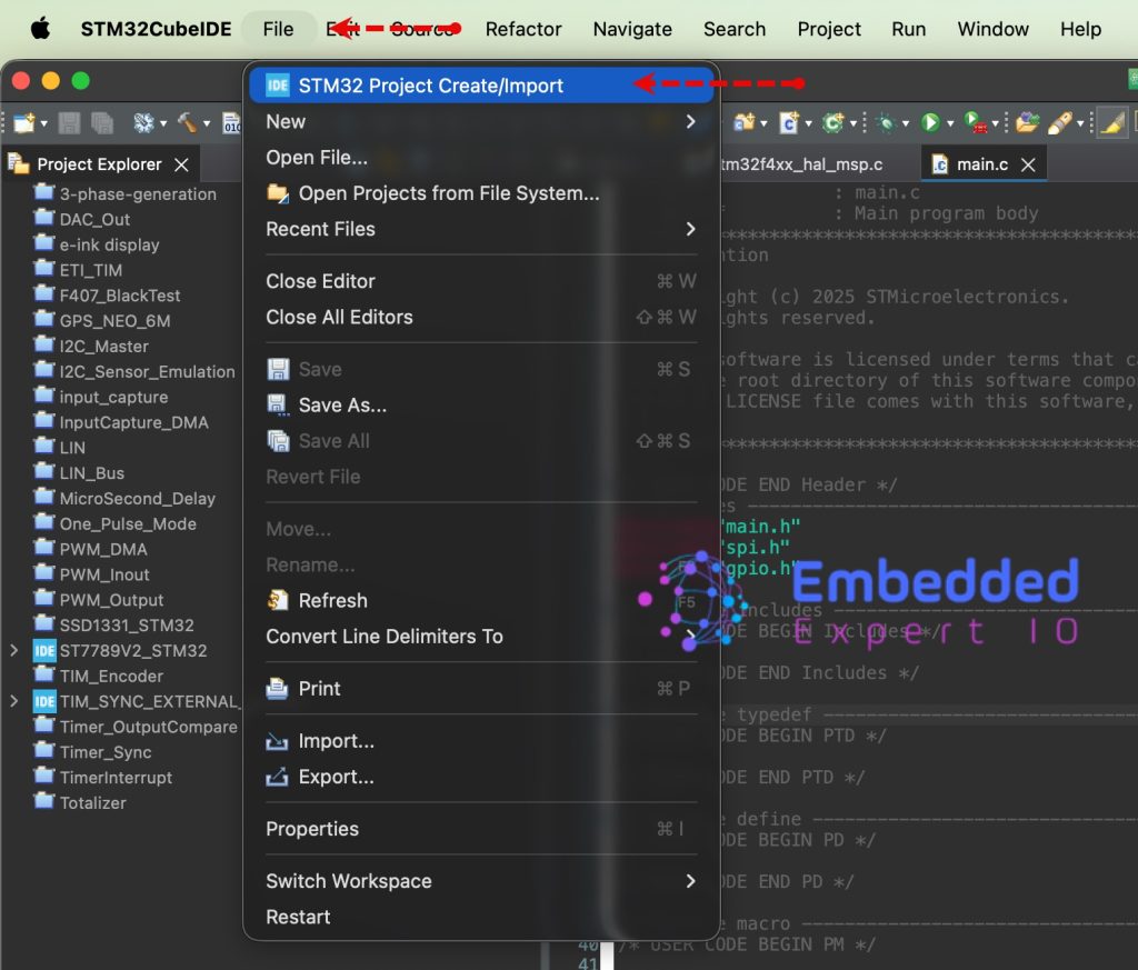
From the IDE, click File and select STM32 Project Create/Import as follows:
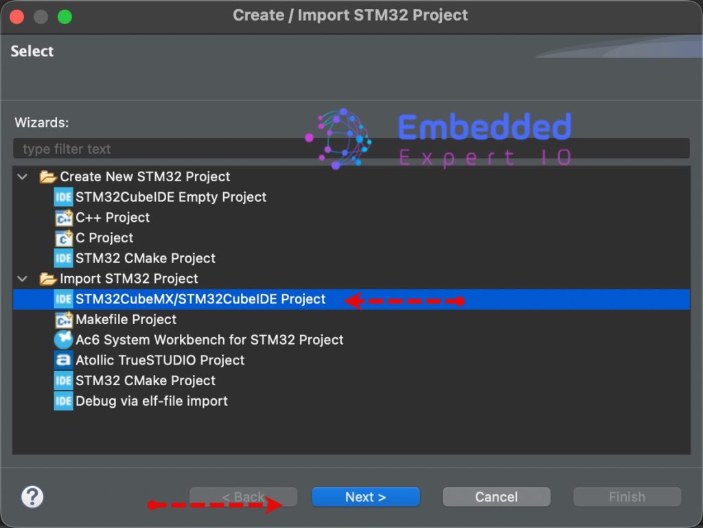
Next, from Import STM32 Project, select STM32CubeMX/STM32CubeIDE Project and click on Next as follows:
Next, select the folder that contains the .ioc file and click on Finish as follows:
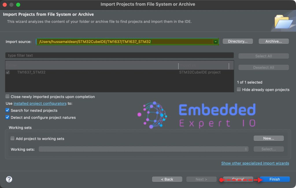
Note: Project name is for reference only.
4. Firmware Development:
The initialization of the pins are similar to blinking LED. However, there are some addition as follows:
LL_AHB1_GRP1_EnableClock(LL_AHB1_GRP1_PERIPH_GPIOC);
This line will enable clock access to GPIOC
GPIO_InitStruct.Pin = LL_GPIO_PIN_13;
GPIO_InitStruct.Mode = LL_GPIO_MODE_INPUT;
GPIO_InitStruct.Pull = LL_GPIO_PULL_NO;
LL_GPIO_Init(GPIOC, &GPIO_InitStruct);
This will initialize PC13 pin as input.
Next, in user code begin PV, declare the following variable:
uint8_t btn_state;
This will hold the state of the button.
In user code begin 3 in while 1 loop:
first, read PC13 state and store it in btn_state variable as follows:
btn_state=LL_GPIO_IsInputPinSet(GPIOC, LL_GPIO_PIN_13);
Next, check if state is low, means the button is pressed and turn on the LED on PA5 and if it is high, turn off the LED as follows:
if(btn_state==0) //Button
	  {
		  LL_GPIO_SetOutputPin(GPIOA, LL_GPIO_PIN_5);
	  }

else //Button is released
	  {
		  LL_GPIO_ResetOutputPin(GPIOA, LL_GPIO_PIN_5);
	  }
Save, build the project and run it as follows:

You may download the project from our github repository from here.
5. Results:
Happy coding 😉
Add Comment