Master the balance between hardware control and code efficiency by leveraging the STM32F4’s Low Layer (LL) drivers for direct register access. This introductory guide walks you through a lean project setup and GPIO configuration to execute a high-performance LED blink with minimal overhead.
In this guide, we shall cover the following:
- Introduction.
- STM32CubeMX setup.
- Importing the project to STM32CubeIDE.
- Firmware Development.
- Results.
1. Introduction:
Embarking on the development of firmware for the STM32F4 series often presents a choice between high-level abstraction and low-level control. While many developers begin their journey with the Hardware Abstraction Layer (HAL), those seeking to extract maximum performance and efficiency from their silicon eventually turn to the Low Layer (LL) drivers. The LL drivers provide a hardware-proximate set of inline functions that map directly to the microcontroller’s registers. Unlike HAL, which manages state and handles complex error checking behind the scenes, LL acts as a thin wrapper over the hardware, offering a “what you see is what you get” approach to firmware engineering.
Why LL is Important
In the world of embedded systems, resources like execution time and memory are often at a premium. The LL drivers are vital for several key reasons:
- Zero-Overhead Performance: Because LL functions are often defined as
inline, they frequently compile down to a single assembly instruction. This eliminates the function-call overhead associated with HAL, making it ideal for high-speed interrupts and time-critical loops. - Minimal Footprint: LL drivers do not maintain internal state variables or large configuration structures. This significantly reduces the Flash and RAM footprint of your application, which is crucial when working on memory-constrained projects.
- Predictability: For engineers who need to know exactly when a bit is toggled or a peripheral is enabled, LL provides transparent access. There are no hidden side effects or background processes, giving the developer total sovereignty over the CPU.
LL vs. HAL: A Comparison
Choosing between HAL and LL is generally a trade-off between development speed and runtime efficiency.
| Feature | HAL (Hardware Abstraction Layer) | LL (Low Layer) |
| Abstraction Level | High; hides register complexity. | Low; direct register mapping. |
| Code Size | Larger due to generic state handling. | Minimal; very small footprint. |
| Execution Speed | Slower; involves multiple function calls. | Optimized; often zero-overhead. |
| Ease of Use | User-friendly; handles peripheral dependencies. | Requires deep datasheet knowledge. |
| Portability | Highly portable across STM32 families. | Less portable; register-specific. |
While HAL is excellent for rapid prototyping and complex middleware integration (like USB or TCP/IP stacks), LL is the preferred choice for drivers where every clock cycle counts. By mastering LL, you gain the ability to write professional-grade, lean firmware that utilizes the STM32F4 hardware to its absolute limit. In this guide, we will leverage this efficiency to set up our environment and execute a precise LED blink.
2. STM32CubeMX Setup:
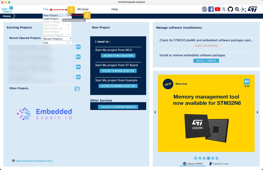
Open STM32CubeMX as start a new project as follows:
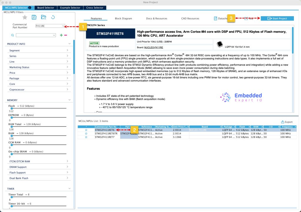
Search for your STM32 MCU, select the MCU and click on Start New Project as follows:
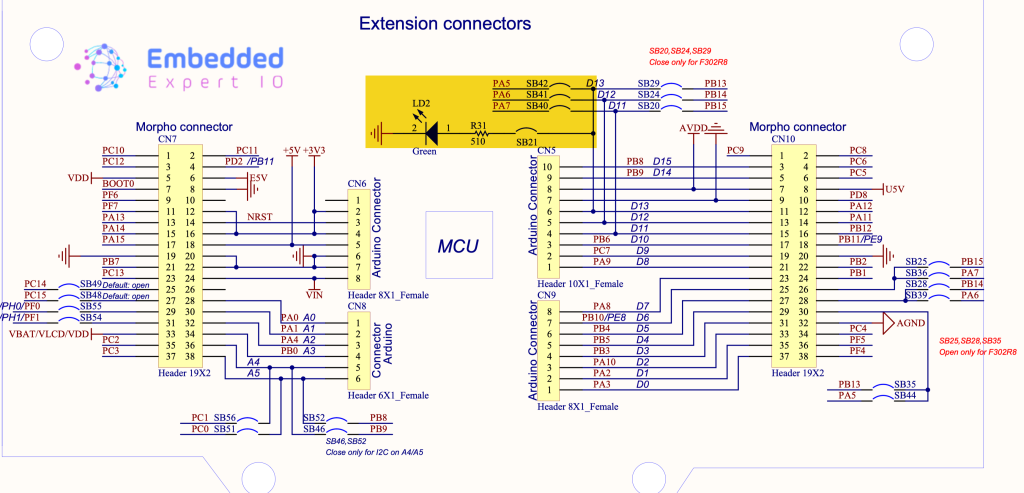
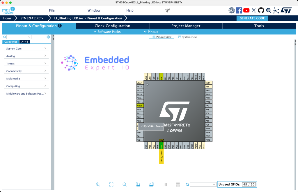
From the user manual of STM32F411 Nucleo-64, we can find that the LD2 is connected to PA5:
Next, set PA5 as output as follows:
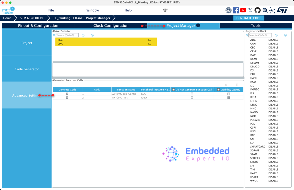
Next, from Project Manager, head to Advanced Settings, set both RCC and GPIO to LL as follows:
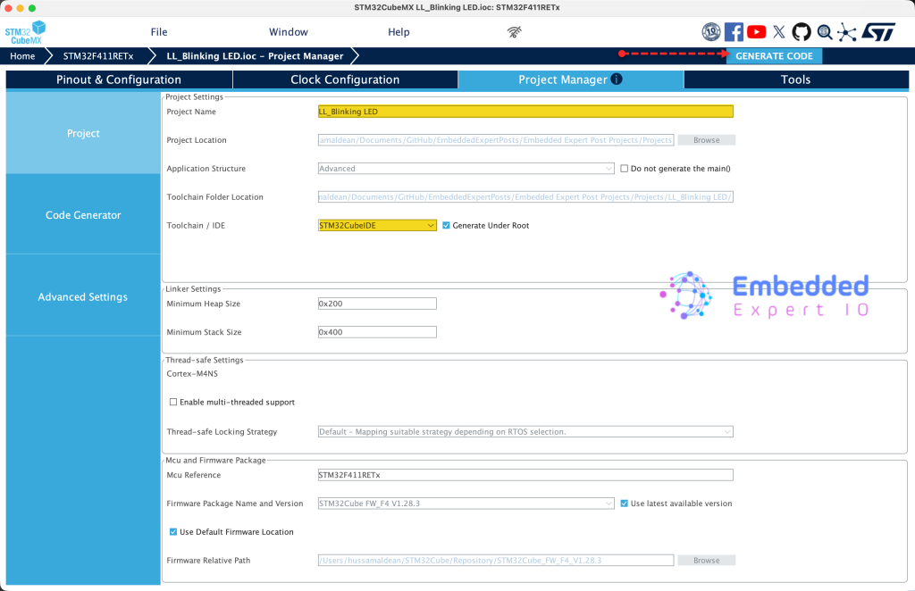
Next, from Project, give the project a name and set toolchain/IDE to STM32CubeIDE and click on Generate Code as follows:
Thats all for STM32CubeMX setup.
3. Importing the Project to STM32CubeIDE:
Open STM32CubeIDE, select your workspace and click on Launch.
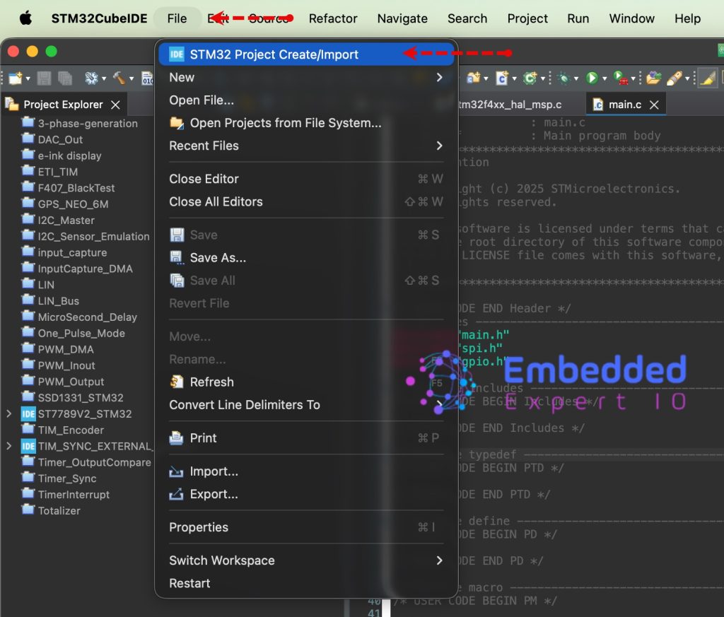
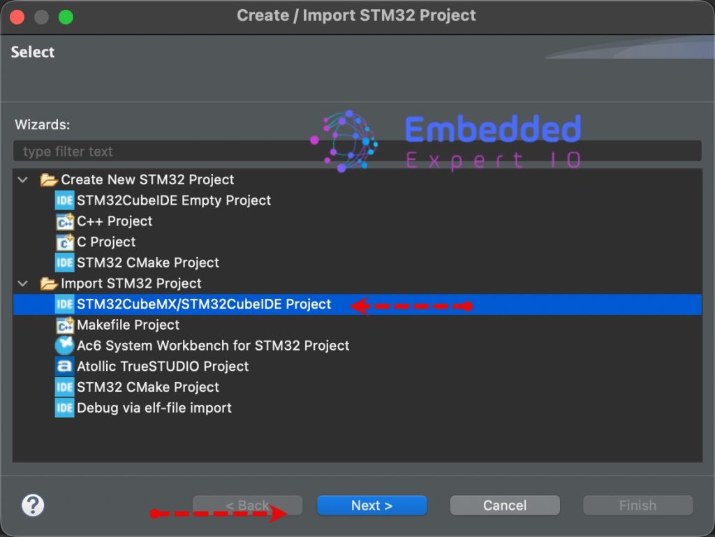
From the IDE, click File and select STM32 Project Create/Import as follows:
Next, from Import STM32 Project, select STM32CubeMX/STM32CubeIDE Project and click on Next as follows:
Next, select the folder that contains the .ioc file and click on Finish as follows:
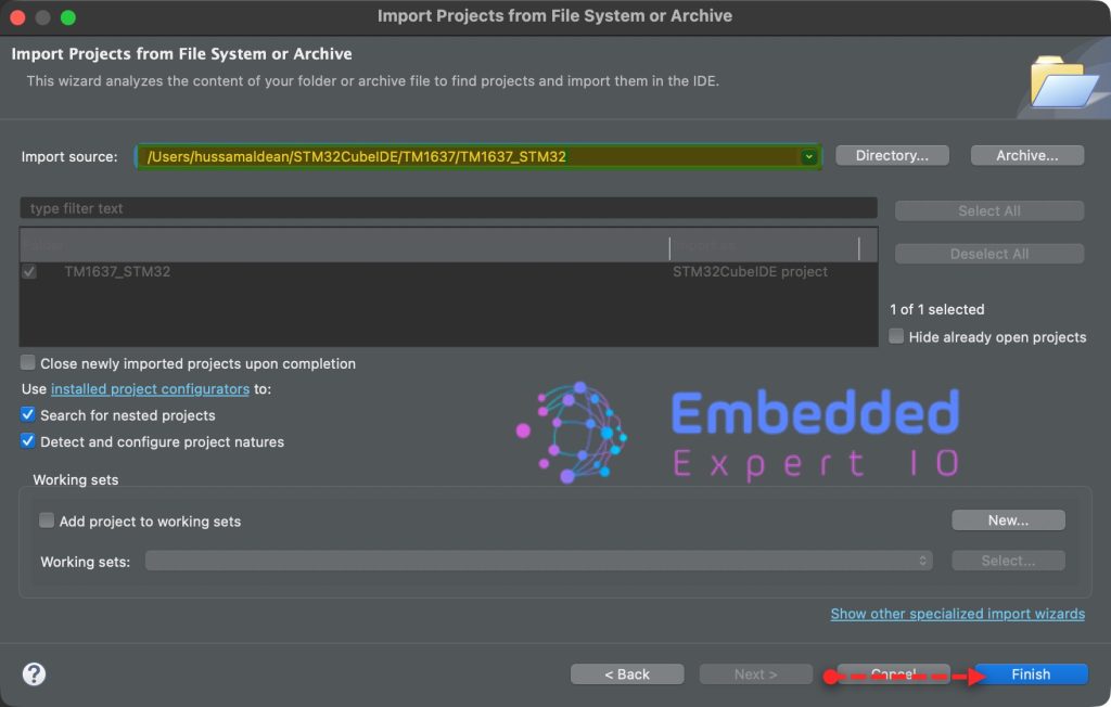
Note: Project name is for reference only.
4. Firmware Development:
Before we develop the firmware, let us explain the generated function.
This function, SystemClock_Config, is the heartbeat of your firmware. Using Low Layer (LL) calls, it manually configures the STM32F4 to run using its internal oscillator. In the world of registers, this is where you define how fast your CPU “thinks” and how it handles memory access.
Phase 1: Flash Memory Latency
LL_FLASH_SetLatency(LL_FLASH_LATENCY_0);
while(LL_FLASH_GetLatency()!= LL_FLASH_LATENCY_0) { }
Flash memory is significantly slower than the CPU. If the CPU clock is high, we must add Wait States (latency) so the Flash can keep up. Since you are configuring a relatively slow clock (16 MHz), LATENCY_0 is used, meaning the CPU can read from Flash instantly without waiting. The while loop is a hardware barrier ensuring the setting is applied before moving on.
Phase 2: Power and Internal Oscillator (HSI)
LL_PWR_SetRegulVoltageScaling(LL_PWR_REGU_VOLTAGE_SCALE1);
LL_RCC_HSI_SetCalibTrimming(16);
LL_RCC_HSI_Enable();
while(LL_RCC_HSI_IsReady() != 1) { }
- Voltage Scaling: This adjusts the internal main voltage regulator to balance power consumption versus performance.
SCALE1is the highest performance mode. - HSI (High-Speed Internal): This enables the internal 16 MHz RC oscillator. You don’t need an external crystal for this. The code trims the factory calibration and waits for the
HSI_IsReadyflag to ensure the clock signal is stable.
Phase 3: Bus Prescalers
LL_RCC_SetAHBPrescaler(LL_RCC_SYSCLK_DIV_1);
LL_RCC_SetAPB1Prescaler(LL_RCC_APB1_DIV_1);
LL_RCC_SetAPB2Prescaler(LL_RCC_APB2_DIV_1);
The STM32 doesn’t just have one clock; it has a hierarchy of buses:
- AHB (Advanced High-performance Bus): Connects the Core to high-speed peripherals (like GPIO).
- APB1/APB2 (Advanced Peripheral Buses): Connects slower peripherals (like UART or I2C).By setting these to
DIV_1, you are running all these buses at the full 16 MHz speed.
Phase 4: System Clock Selection
LL_RCC_SetSysClkSource(LL_RCC_SYS_CLKSOURCE_HSI);
while(LL_RCC_GetSysClkSource() != LL_RCC_SYS_CLKSOURCE_STATUS_HSI) { }
This is the “switch-over” moment. You tell the MCU to stop using its default startup clock and start using the HSI as the main SYSCLK. The loop confirms the hardware has successfully made the transition.
Phase 5: Timekeeping and Core Updates
LL_Init1msTick(16000000);
LL_SetSystemCoreClock(16000000);
- LL_Init1msTick: Configures the SysTick timer to generate an interrupt every 1ms based on the 16 MHz frequency. This is vital for functions like
LL_mDelay. - LL_SetSystemCoreClock: Updates the global
SystemCoreClockvariable. This doesn’t change hardware speed, but it tells the CMSIS software layers exactly how fast the hardware is running so timing calculations remain accurate.
The MX_GPIO_Init function handles the fundamental setup of the microcontroller’s hardware pins. Using the Low Layer (LL) library, it takes a structured approach to transform a generic silicon pin into a functional digital output.
1. Enabling the Peripheral Clock
LL_AHB1_GRP1_EnableClock(LL_AHB1_GRP1_PERIPH_GPIOA);
On the STM32F4, peripherals are disabled by default to save power. Before you can modify any registers in Port A, you must enable its clock on the AHB1 (Advanced High-performance Bus). Without this line, any subsequent commands to GPIOA will be ignored by the hardware.
2. Ensuring a Safe Initial State
LL_GPIO_ResetOutputPin(GPIOA, LL_GPIO_PIN_5);
It is a professional “best practice” to define the pin state before it becomes an output. By resetting Pin 5, you ensure that as soon as the pin is initialized, it starts at 0V (Logic Low), preventing any accidental “glitches” or brief power-on pulses to whatever hardware is connected.
3. Configuring the GPIO Structure
The function uses the LL_GPIO_InitTypeDef structure to define the physical characteristics of the pin. This is essentially a template that gets translated into register values by the LL_GPIO_Init function.
| Parameter | Value | Description |
| Pin | LL_GPIO_PIN_5 | Targets the specific physical pin (PA5). |
| Mode | OUTPUT | Sets the pin to drive a signal out (rather than reading one in). |
| Speed | FREQ_LOW | Reduces the “slew rate” (how fast the voltage rises/falls). Low frequency reduces EMI (Electromagnetic Interference) and is perfect for an LED. |
| OutputType | PUSHPULL | The pin can actively drive the signal to both VCC (High) and Ground (Low). |
| Pull | PULL_NO | Disables internal resistors. Since the pin is in Push-Pull mode, it doesn’t need internal help to stay at a logic level. |
4. Hardware Application
LL_GPIO_Init(GPIOA, &GPIO_InitStruct);
This final call is where the magic happens. It takes all the settings defined in your GPIO_InitStruct and writes them into the MODER, OSPEEDR, OTYPER, and PUPDR registers of Port A. Once this line executes, PA5 is officially ready to drive your LED.
Next, in while 1 loop, in user code begin 3, toggle the LED state as follows:
LL_GPIO_TogglePin(GPIOA, LL_GPIO_PIN_5);
Delay by 1 second:
LL_mDelay(1000);
Alternatively, you can use the following to toggle the state of the LED as follows:
To set the pin to high:
LL_GPIO_SetOutputPin(GPIOA, LL_GPIO_PIN_5);
To set the pin low:
LL_GPIO_ResetOutputPin(GPIOA, LL_GPIO_PIN_5);
Note that set and reset function are separated. This will improve the performance of the MUC.
Save, build the project and run it as follows:

You may download the project from our github repository from here.
5. Results:
You should get something similar to this:
Happy coding 😉
Add Comment