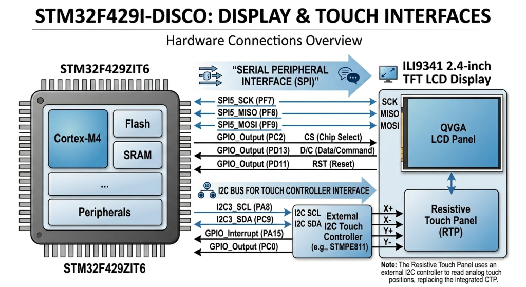
Part 4 focuses on initializing the touch controller and establishing communication between the STM32 and the touch interface hardware. It also demonstrates how to read the controller’s device ID to verify correct configuration and ensure the touch controller is responding properly.
In this guide, we shall cover the following:
- STM32CubeMX configuration.
- Firmware Development.
- Results.
1. STM32CubeMX Configuration:
Open the previous project in STM32CubeMX.
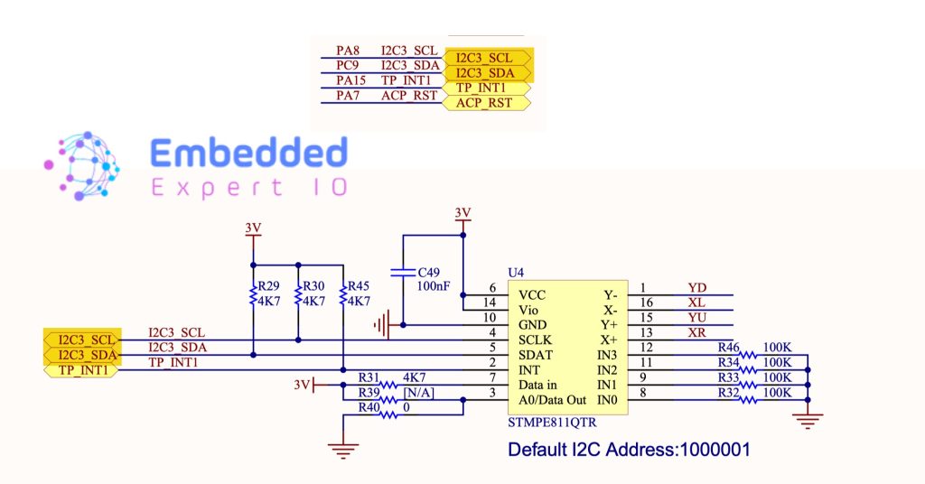
First from the schematic of the board, we can determine the pins for the touch controller as follows:
Note: Currently, we are not enabling the interrupt capability of the touch controller.
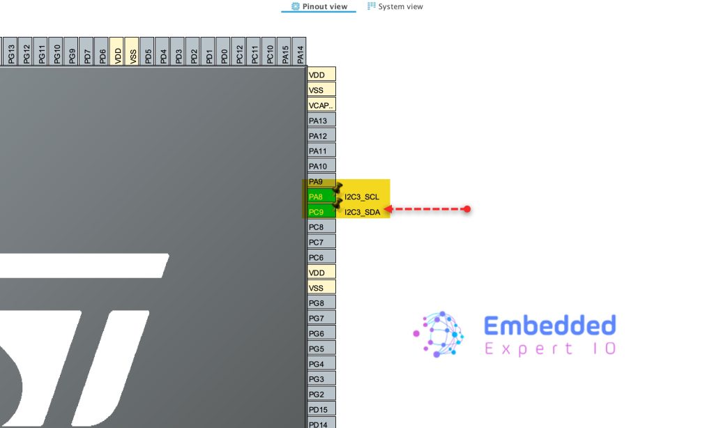
Hence, we need to enable PA8 and PC9 as I2C3_SCL and I2C3_SDA respectively as follows:
Next, from the connectivity, enable I2C3 and keep the parameters as default as follows:
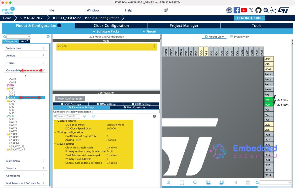
Thats all for the configuration.
Click on Generate Code to generate the new configuration.

2. Firmware Development:
First, we need to create new source and header files.
To create Source file, right click on Src folder and add new source file as following:
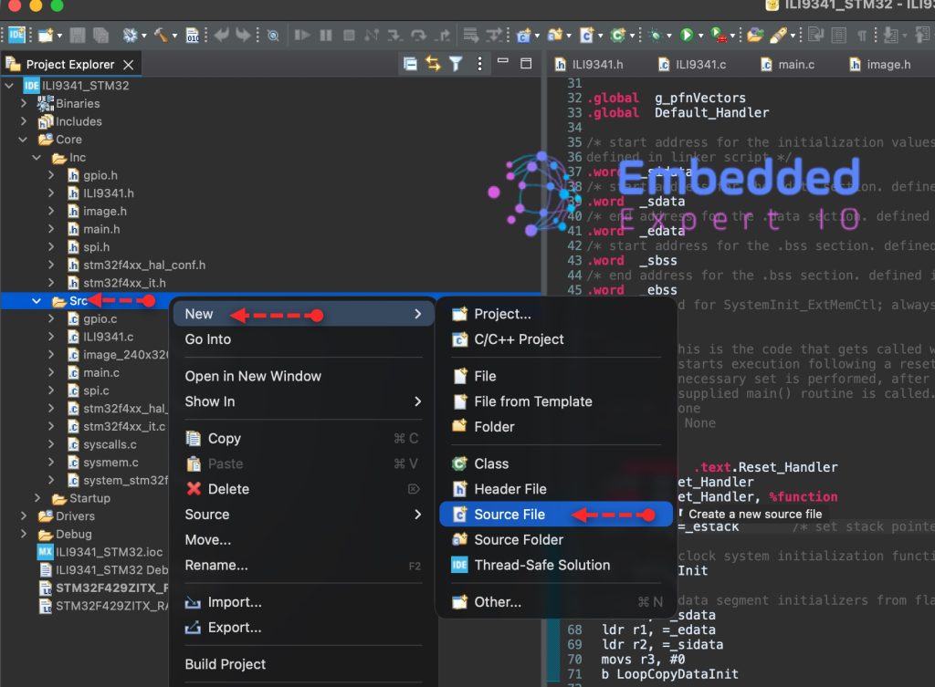
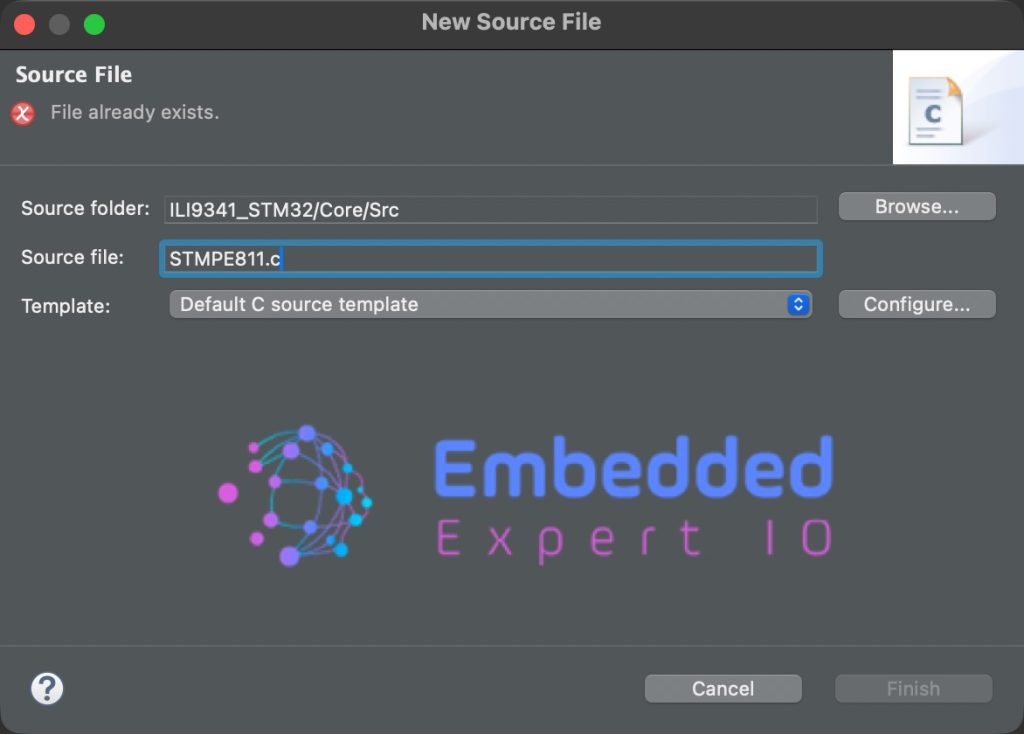
Give a name for the source file, we shall name it as STMPE811.c as following:
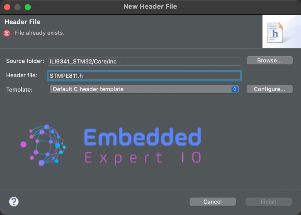
In similar manner, right click on Inc folder and add new header file with name of STMPE811.h as follows:
In STMPE811.h, include the following header files:
#include "stdint.h"
Next, declare a macro that holds the address of the touch controller as follows:
#define deviceAddress 0x41<<1
Note: the address is mentioned in the schematic of the board.
The reason behind shift left by 1 to accommodate the read/write bit.
Next, declare enum to hold touched and untouched states as follows:
typedef enum TouchDetect
{
	touched =1,
	no_touch=0

}TouchDetect_t;
Next, macros that will hold registers of the touch controller as follows:
#define STMPE811_REG_CHIP_ID			0x00 /*Chip ID Register*/
#define STMPE811_REG_ID_VER				0x01 /*ID Revision Register*/
#define STMPE811_REG_SYS_CTRL2 			0x04 /*Clock control*/
#define STMPE811_REG_SYS_CTRL1 			0x03 /*Reset control*/
#define STMPE811_REG_IO_AF              0x17 /*Alternate function register*/
#define STMPE811_REG_ADC_CTRL1          0x20 /*ADC control*/
#define STMPE811_REG_ADC_CTRL2          0x21 /*ADC control*/
#define STMPE811_REG_TSC_CFG            0x41 /*Touch Configuration*/
#define STMPE811_REG_FIFO_TH            0x4A /*FIFO threshold*/
#define STMPE811_REG_FIFO_STA           0x4B /*FIFO status*/
#define STMPE811_REG_TSC_FRACT_XYZ      0x56 /*Touchscreen controller FRACTION_Z*/
#define STMPE811_REG_TSC_I_DRIVE        0x58 /*Touchscreen controller drive*/
#define STMPE811_REG_TSC_CTRL           0x40 /*touchscreen controller control register*/
#define STMPE811_REG_INT_CTRL			0x09 /*Interrupt control register*/
#define STMPE811_REG_INT_EN				0x0A /*Interrupt enable register*/
#define STMPE811_REG_INT_STA            0x0B /*Interrupt status register*/
#define STMPE811_REG_TSC_DATA_INC       0x57 /*Touchscreen controller DATA Incremental*/
#define STMPE811_REG_TSC_DATA_NON_INC   0xD7 /*Touchscreen controller DATA Non-Incremental*/
#define STMPE811_REG_FIFO_SIZE          0x4C /*FIFO size*/

/*IO expander facilities*/
#define STMPE811_ADC_FCT                0x01
#define STMPE811_TS_FCT                 0x02
#define STMPE811_IO_FCT                 0x04
#define STMPE811_TEMPSENS_FCT           0x08


/* Touch Screen Pins definition */
#define STMPE811_TOUCH_YD               STMPE811_PIN_7
#define STMPE811_TOUCH_XD               STMPE811_PIN_6
#define STMPE811_TOUCH_YU               STMPE811_PIN_5
#define STMPE811_TOUCH_XU               STMPE811_PIN_4
#define STMPE811_TOUCH_IO_ALL           0x00

/* IO Pins definition */
#define STMPE811_PIN_0                  0x01
#define STMPE811_PIN_1                  0x02
#define STMPE811_PIN_2                  0x04
#define STMPE811_PIN_3                  0x08
#define STMPE811_PIN_4                  0x10
#define STMPE811_PIN_5                  0x20
#define STMPE811_PIN_6                  0x40
#define STMPE811_PIN_7                  0x80
#define STMPE811_PIN_ALL                0xFF

#define STMPE811_TS_CTRL_ENABLE         0x01
#define STMPE811_TS_CTRL_STATUS         0x80
Next, declare touch enable function, which will initialize the touch controller as follows:
void STMPE811_Touch_Enable(void);
Finally, a function to get the device ID as follows:
uint16_t getID(void);
That’s all for the header file.
Next, in STMPE811.c, include the following header files:
#include "STMPE811.h"

#include "i2c.h"
Declare the following which will allow us to read/write from/to chip by calling simple function as follows:
static void STMPE811_WriteReg(uint8_t reg, uint8_t data)
{
    HAL_I2C_Mem_Write(&hi2c3,deviceAddress,reg,I2C_MEMADD_SIZE_8BIT,&data,1,HAL_MAX_DELAY);
}

static void STMPE811_ReadReg(uint8_t reg, uint8_t *data)
{
    HAL_I2C_Mem_Read(&hi2c3,deviceAddress,reg,I2C_MEMADD_SIZE_8BIT,data,1,HAL_MAX_DELAY);
}

static void STMPE811_ReadMulti(uint8_t reg, uint8_t *data, uint16_t len)
{
	HAL_I2C_Mem_Read(&hi2c3,deviceAddress ,reg,I2C_MEMADD_SIZE_8BIT,data,len,HAL_MAX_DELAY);
}
Next, touch enable function:
void STMPE811_Touch_Enable(void)
{
    uint8_t mode;

    /* Power Down the STMPE811 */
    STMPE811_WriteReg(STMPE811_REG_SYS_CTRL1, 0x02);
    HAL_Delay(10);

    /* Power On (reset registers) */
    STMPE811_WriteReg(STMPE811_REG_SYS_CTRL1, 0x00);
    HAL_Delay(2);

    /* Disable GPIO clock */
    STMPE811_ReadReg(STMPE811_REG_SYS_CTRL2, &mode);
    mode &= ~(STMPE811_IO_FCT);
    STMPE811_WriteReg(STMPE811_REG_SYS_CTRL2, mode);

    /* Select TSC pins in alternate mode */
    STMPE811_WriteReg(STMPE811_REG_IO_AF, STMPE811_TOUCH_IO_ALL);

    /* Enable ADC and Touch */
    mode &= ~(STMPE811_TS_FCT | STMPE811_ADC_FCT);
    STMPE811_WriteReg(STMPE811_REG_SYS_CTRL2, mode);

    /* ADC configuration */
    STMPE811_WriteReg(STMPE811_REG_ADC_CTRL1, 0x49);
    HAL_Delay(2);

    STMPE811_WriteReg(STMPE811_REG_ADC_CTRL2, 0x01);

    /* Touch configuration
       AVG = 8 samples
       Delay = 500us
       Panel driver = 500us
    */
    STMPE811_WriteReg(STMPE811_REG_TSC_CFG, 0xDA);

    /* FIFO threshold = 1 */
    STMPE811_WriteReg(STMPE811_REG_FIFO_TH, 0x01);

    /* Reset FIFO */
    STMPE811_WriteReg(STMPE811_REG_FIFO_STA, 0x01);
    STMPE811_WriteReg(STMPE811_REG_FIFO_STA, 0x00);

    /* Pressure measurement configuration */
    STMPE811_WriteReg(STMPE811_REG_TSC_FRACT_XYZ, 0x07);

    /* Drive current = 50mA */
    STMPE811_WriteReg(STMPE811_REG_TSC_I_DRIVE, 0x01);

    /* Enable Touch Screen Controller */
    STMPE811_WriteReg(STMPE811_REG_TSC_CTRL, 0x01);

    /* Clear interrupts */
    STMPE811_WriteReg(STMPE811_REG_INT_STA, 0xFF);

    HAL_Delay(5);
}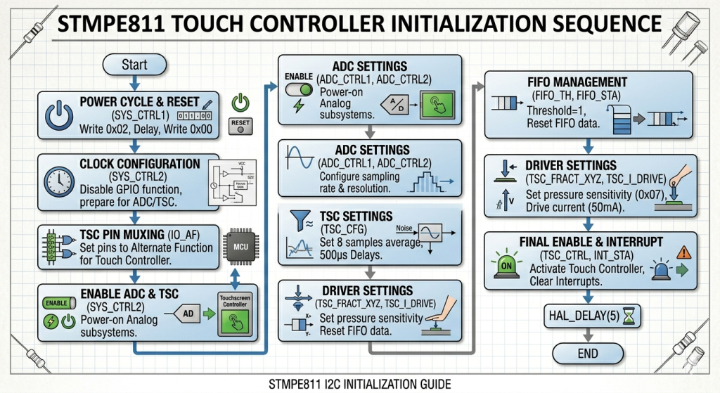
This initialization function prepares the STMPE811 to act as a dedicated touch co-processor, offloading the heavy lifting of signal processing from your STM32.
Functional Breakdown
- Reset & Power: It performs a hardware reset via
SYS_CTRL1and enables the internal clocks for the ADC and Touch subsystems, while disabling unused GPIO functions to save power. - Signal Conditioning: It configures the controller to average 8 samples per touch point. This is vital for resistive screens to filter out electrical noise and provide stable, “jitter-free” coordinates.
- Hardware Mapping: It switches the necessary pins from general-purpose mode to Alternate Function mode, physically connecting the resistive panel layers to the internal sensing circuitry.
- Data Management: It resets the internal FIFO buffer and sets a threshold of 1, ensuring the STM32 is notified immediately when a new, valid touch coordinate is available.
- Final Activation: After setting the panel drive current (50mA) and pressure sensitivity, it enables the Touch Screen Controller (TSC) and clears all interrupt flags to start with a clean state.
Why these delays matter?
The HAL_Delay calls allow the internal analog components (like the voltage reference and charge pumps) to stabilize. Without them, the first few touch coordinates would likely be inaccurate or “ghost” touches.
Finally, the getID function as follows:
uint16_t getID(void)
{
    uint8_t data[2];

    STMPE811_ReadMulti(STMPE811_REG_CHIP_ID, data, 2);

    return (data[0] << 8) | data[1];
}
In main.c, include STMPE811 header file as follows:
#include "STMPE811.h"
In main function, enable the touch as follows:
STMPE811_Touch_Enable();
Get the ID as follows:
uint16_t ID=0; //Global variable
ID=getID();
Thats all for the firmware.
Save, build the project and run it as follows:

3. Results:
Start a debug session and add ID variable to the live expression and you should get the following:

Which match the one in the datasheet of the touch controller:

In part 5, we shall get the touch values.
Stay tuned.
Happy coding 😉
Add Comment