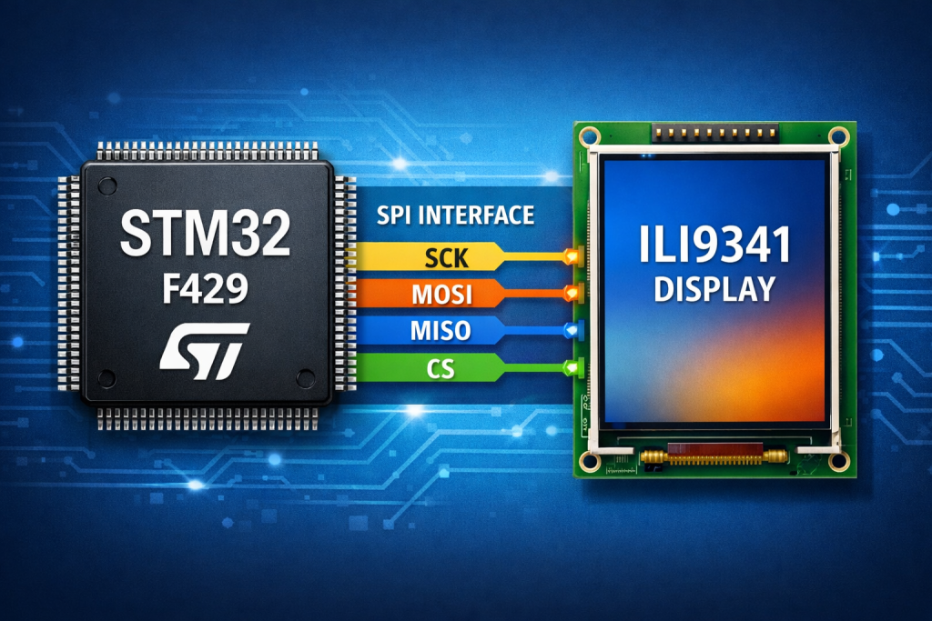
Part 2 focuses on initializing the display controller and establishing reliable communication between the STM32F429 and the ILI9341 over SPI. It then introduces the fundamental draw pixel routine, forming the basis for all higher-level graphics operations.
In this guide, we shall cover the following:
- Creating source and header file.
- Developing the header file.
- Developing the source file.
- Main.c code.
- Results.
5. Creating Source and Header File:
First, we need to create new source and header files.
To create Source file, right click on Src folder and add new source file as following:
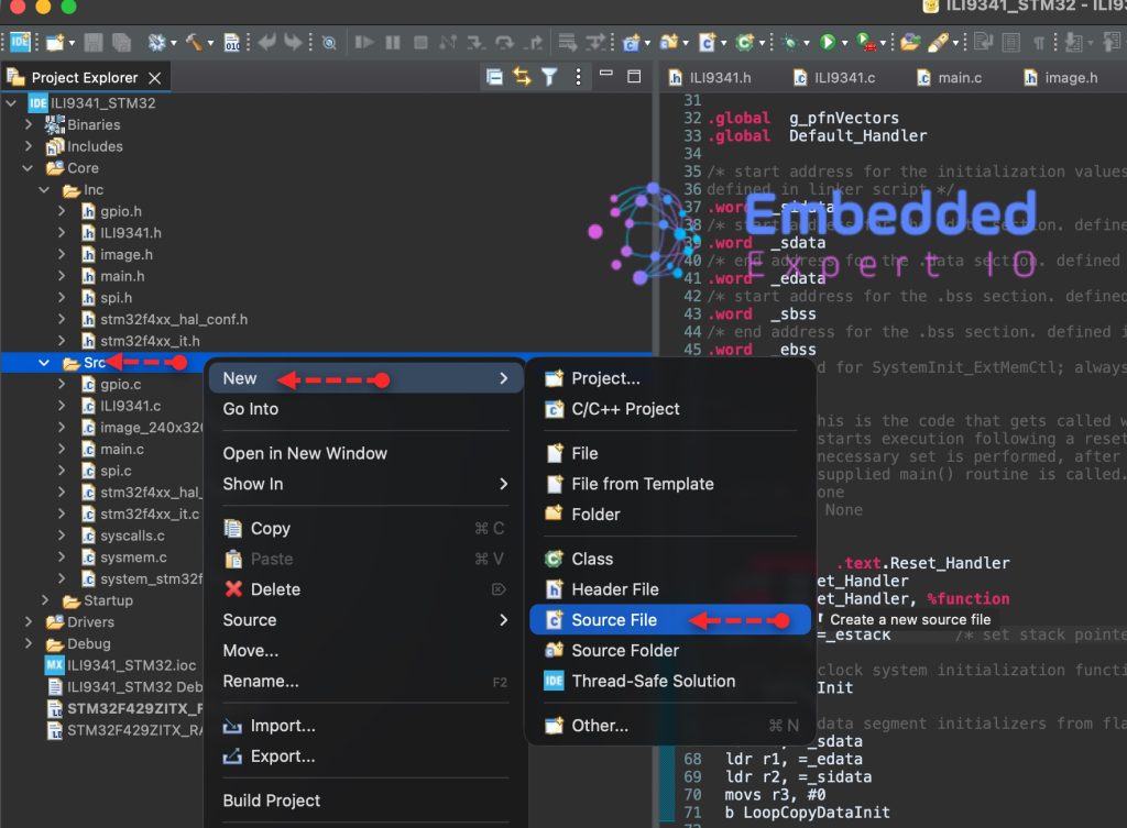
Give a name for the source file, we shall name it as ILI9341.c as following:

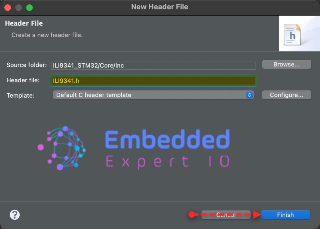
In similar manner, right click on Inc folder and add new header file with name of ILI9341.h as follows:
6. Developing the Header File:
Open ILI9341 header file.
We start by including the main.h and spi.h as follows:
#include "main.h"

#include "spi.h"
Next, declare the following enumeration to handle screen rotation as follows:
typedef enum {
	ROTATE_0,
	ROTATE_90,
	ROTATE_180,
	ROTATE_270
} LCD_Horizontal_t;
Next, declare the following two functions:
A function that initialize the LCD and set the desired rotation
void ILI9341_Init(LCD_Horizontal_t rot);
A function that will draw a single pixel and takes the pixel coordinates and the color as follows:
void ILI9341_WritePixel(uint16_t x, uint16_t y, uint16_t color);
Hence, the header file as follows:
#ifndef INC_ILI9341_H_
#define INC_ILI9341_H_

#include "main.h"

#include "spi.h"

typedef enum {
	ROTATE_0,
	ROTATE_90,
	ROTATE_180,
	ROTATE_270
} LCD_Horizontal_t;

void ILI9341_Init(LCD_Horizontal_t rot);

void ILI9341_WritePixel(uint16_t x, uint16_t y, uint16_t color);

#endif /* INC_ILI9341_H_ */
7. Developing the Source File:
Open ILI9341.c source file.
Include the ILI9341 header file as follows:
#include "ILI9341.h"
Next, declare the following functions that will handle CS, DC, RST as follows:
static void CS_Deselect()
{
	HAL_GPIO_WritePin(CS_GPIO_Port, CS_Pin, SET);
}

static void CS_Select()
{
	HAL_GPIO_WritePin(CS_GPIO_Port, CS_Pin, RESET);
}

static void RST_HIGH()
{
	HAL_GPIO_WritePin(RST_GPIO_Port, RST_Pin, SET);
}

static void RST_LOW()
{
	HAL_GPIO_WritePin(RST_GPIO_Port, RST_Pin, RESET);
}

static void DC_HIGH()
{
	HAL_GPIO_WritePin(DC_GPIO_Port, DC_Pin, SET);
}

static void DC_LOW()
{
	HAL_GPIO_WritePin(DC_GPIO_Port, DC_Pin, RESET);
}
Next, hardware reset for the display, the function as follows:
static void Reset(void)
{
	RST_HIGH();
    HAL_Delay(100);
    RST_LOW();
    HAL_Delay(100);
    RST_HIGH();
    HAL_Delay(100);
}
Next, write data, command and 16-bit data functions as follows:
static void WriteData(uint8_t data)
{
	CS_Select();
	DC_HIGH();

	HAL_SPI_Transmit(&hspi5, &data, 1, 10);

	CS_Deselect();

}

static void WriteCommand(uint8_t Command)
{
	CS_Select();
	DC_LOW();

	HAL_SPI_Transmit(&hspi5, &Command, 1, 10);

	CS_Deselect();

}

static void WriteData16Bit(uint16_t data)
{
	CS_Select();
	DC_HIGH();

	uint8_t data16_bit[2]={(data>>8)&0xFF, data&0xFF};

	HAL_SPI_Transmit(&hspi5, data16_bit, 2, 10);

	CS_Deselect();

}
These functions are identical for any LCD driver such as ILI9341, ST7789 etc.
Next, the function that shall set the rotation of the display:
static void LCD_direction(LCD_Horizontal_t direction)
{
	switch (direction) {
	case ROTATE_0:
		WriteCommand(0x36);
		WriteData(0x48);
		break;
	case ROTATE_90:
		WriteCommand(0x36);
		WriteData(0x28);
		break;
	case ROTATE_180:
		WriteCommand(0x36);
		WriteData(0x88);
		break;
	case ROTATE_270:
		WriteCommand(0x36);
		WriteData(0xE8);
		break;
	}
}
Display initialization function:
void ILI9341_Init(LCD_Horizontal_t rot)
{
	Reset();
	HAL_Delay(800);

	/* Power Control A */
	WriteCommand(0xCB);
	WriteData(0x39);
	WriteData(0x2C);
	WriteData(0x00);
	WriteData(0x34);
	WriteData(0x02);
	/* Power Control B */
	WriteCommand(0xCF);
	WriteData(0x00);
	WriteData(0xC1);
	WriteData(0x30);
	/* Driver timing control A */
	WriteCommand(0xE8);
	WriteData(0x85);
	WriteData(0x00);
	WriteData(0x78);
	/* Driver timing control B */
	WriteCommand(0xEA);
	WriteData(0x00);
	WriteData(0x00);
	/* Power on Sequence control */
	WriteCommand(0xED);
	WriteData(0x64);
	WriteData(0x03);
	WriteData(0x12);
	WriteData(0x81);
	/* Pump ratio control */
	WriteCommand(0xF7);
	WriteData(0x20);
	/* Power Control 1 */
	WriteCommand(0xC0);
	WriteData(0x10);
	/* Power Control 2 */
	WriteCommand(0xC1);
	WriteData(0x10);
	/* VCOM Control 1 */
	WriteCommand(0xC5);
	WriteData(0x3E);
	WriteData(0x28);
	/* VCOM Control 2 */
	WriteCommand(0xC7);
	WriteData(0x86);
	/* VCOM Control 2 */
	WriteCommand(0x36);
	WriteData(0x48);
	/* Pixel Format Set */
	WriteCommand(0x3A);
	WriteData(0x55);    //16bit
	WriteCommand(0xB1);
	WriteData(0x00);
	WriteData(0x18);

	/* Display Function Control */
	WriteCommand(0xB6);
	WriteData(0x08);
	WriteData(0x82);
	WriteData(0x27);
	/* 3GAMMA FUNCTION DISABLE */
	WriteCommand(0xF2);
	WriteData(0x00);
	/* GAMMA CURVE SELECTED */
	WriteCommand(0x26); //Gamma set
	WriteData(0x01); 	//Gamma Curve (G2.2)
	//Positive Gamma  Correction
	WriteCommand(0xE0);
	WriteData(0x0F);
	WriteData(0x31);
	WriteData(0x2B);
	WriteData(0x0C);
	WriteData(0x0E);
	WriteData(0x08);
	WriteData(0x4E);
	WriteData(0xF1);
	WriteData(0x37);
	WriteData(0x07);
	WriteData(0x10);
	WriteData(0x03);
	WriteData(0x0E);
	WriteData(0x09);
	WriteData(0x00);
	//Negative Gamma  Correction
	WriteCommand(0xE1);
	WriteData(0x00);
	WriteData(0x0E);
	WriteData(0x14);
	WriteData(0x03);
	WriteData(0x11);
	WriteData(0x07);
	WriteData(0x31);
	WriteData(0xC1);
	WriteData(0x48);
	WriteData(0x08);
	WriteData(0x0F);
	WriteData(0x0C);
	WriteData(0x31);
	WriteData(0x36);
	WriteData(0x0F);
	//EXIT SLEEP
	WriteCommand(0x11);

	HAL_Delay(120);

	//TURN ON DISPLAY
	WriteCommand(0x29);
	HAL_Delay(10);
	WriteData(0x2C);
	HAL_Delay(10);
	LCD_direction(rot);

}
The initialization sequence has been taken from here.
Next, setWindow function:
static void ILI9341_SetWindow(uint16_t start_x, uint16_t start_y, uint16_t end_x, uint16_t end_y)
{
	// Set Window
	WriteCommand(0x2a);
	WriteData(start_x >> 8);
	WriteData(0xFF & start_x);
	WriteData(end_x >> 8);
	WriteData(0xFF & end_x);

	WriteCommand(0x2b);
	WriteData(start_y >> 8);
	WriteData(0xFF & start_y);
	WriteData(end_y >> 8);
	WriteData(0xFF & end_y);

}
The set window (also called address window or drawing region) function is critical because it defines exactly where in the display’s GRAM the incoming pixel data will be written. On controllers like the ILI9341, you don’t send X/Y coordinates for every pixel—instead, you configure a rectangular region once, and then stream pixel data sequentially, which the controller automatically maps across that area.
Next, draw pixel function:
void ILI9341_WritePixel(uint16_t x, uint16_t y, uint16_t color)
{
	ILI9341_SetWindow(x, y, x, y);

	WriteCommand(0x2c);

	WriteData16Bit(color);

}
Hence, the source file as follows:
#include "ILI9341.h"


static void CS_Deselect()
{
	HAL_GPIO_WritePin(CS_GPIO_Port, CS_Pin, SET);
}

static void CS_Select()
{
	HAL_GPIO_WritePin(CS_GPIO_Port, CS_Pin, RESET);
}

static void RST_HIGH()
{
	HAL_GPIO_WritePin(RST_GPIO_Port, RST_Pin, SET);
}

static void RST_LOW()
{
	HAL_GPIO_WritePin(RST_GPIO_Port, RST_Pin, RESET);
}

static void DC_HIGH()
{
	HAL_GPIO_WritePin(DC_GPIO_Port, DC_Pin, SET);
}

static void DC_LOW()
{
	HAL_GPIO_WritePin(DC_GPIO_Port, DC_Pin, RESET);
}

static void Reset(void)
{
	RST_HIGH();
    HAL_Delay(100);
    RST_LOW();
    HAL_Delay(100);
    RST_HIGH();
    HAL_Delay(100);
}

static void WriteData(uint8_t data)
{
	CS_Select();
	DC_HIGH();

	HAL_SPI_Transmit(&hspi5, &data, 1, 10);

	CS_Deselect();

}

static void WriteCommand(uint8_t Command)
{
	CS_Select();
	DC_LOW();

	HAL_SPI_Transmit(&hspi5, &Command, 1, 10);

	CS_Deselect();

}

static void WriteData16Bit(uint16_t data)
{
	CS_Select();
	DC_HIGH();

	uint8_t data16_bit[2]={(data>>8)&0xFF, data&0xFF};

	HAL_SPI_Transmit(&hspi5, data16_bit, 2, 10);

	CS_Deselect();

}


static void LCD_direction(LCD_Horizontal_t direction)
{
	switch (direction) {
	case ROTATE_0:
		WriteCommand(0x36);
		WriteData(0x48);
		break;
	case ROTATE_90:
		WriteCommand(0x36);
		WriteData(0x28);
		break;
	case ROTATE_180:
		WriteCommand(0x36);
		WriteData(0x88);
		break;
	case ROTATE_270:
		WriteCommand(0x36);
		WriteData(0xE8);
		break;
	}
}


void ILI9341_Init(LCD_Horizontal_t rot)
{
	Reset();
	HAL_Delay(800);

	/* Power Control A */
	WriteCommand(0xCB);
	WriteData(0x39);
	WriteData(0x2C);
	WriteData(0x00);
	WriteData(0x34);
	WriteData(0x02);
	/* Power Control B */
	WriteCommand(0xCF);
	WriteData(0x00);
	WriteData(0xC1);
	WriteData(0x30);
	/* Driver timing control A */
	WriteCommand(0xE8);
	WriteData(0x85);
	WriteData(0x00);
	WriteData(0x78);
	/* Driver timing control B */
	WriteCommand(0xEA);
	WriteData(0x00);
	WriteData(0x00);
	/* Power on Sequence control */
	WriteCommand(0xED);
	WriteData(0x64);
	WriteData(0x03);
	WriteData(0x12);
	WriteData(0x81);
	/* Pump ratio control */
	WriteCommand(0xF7);
	WriteData(0x20);
	/* Power Control 1 */
	WriteCommand(0xC0);
	WriteData(0x10);
	/* Power Control 2 */
	WriteCommand(0xC1);
	WriteData(0x10);
	/* VCOM Control 1 */
	WriteCommand(0xC5);
	WriteData(0x3E);
	WriteData(0x28);
	/* VCOM Control 2 */
	WriteCommand(0xC7);
	WriteData(0x86);
	/* VCOM Control 2 */
	WriteCommand(0x36);
	WriteData(0x48);
	/* Pixel Format Set */
	WriteCommand(0x3A);
	WriteData(0x55);    //16bit
	WriteCommand(0xB1);
	WriteData(0x00);
	WriteData(0x18);

	/* Display Function Control */
	WriteCommand(0xB6);
	WriteData(0x08);
	WriteData(0x82);
	WriteData(0x27);
	/* 3GAMMA FUNCTION DISABLE */
	WriteCommand(0xF2);
	WriteData(0x00);
	/* GAMMA CURVE SELECTED */
	WriteCommand(0x26); //Gamma set
	WriteData(0x01); 	//Gamma Curve (G2.2)
	//Positive Gamma  Correction
	WriteCommand(0xE0);
	WriteData(0x0F);
	WriteData(0x31);
	WriteData(0x2B);
	WriteData(0x0C);
	WriteData(0x0E);
	WriteData(0x08);
	WriteData(0x4E);
	WriteData(0xF1);
	WriteData(0x37);
	WriteData(0x07);
	WriteData(0x10);
	WriteData(0x03);
	WriteData(0x0E);
	WriteData(0x09);
	WriteData(0x00);
	//Negative Gamma  Correction
	WriteCommand(0xE1);
	WriteData(0x00);
	WriteData(0x0E);
	WriteData(0x14);
	WriteData(0x03);
	WriteData(0x11);
	WriteData(0x07);
	WriteData(0x31);
	WriteData(0xC1);
	WriteData(0x48);
	WriteData(0x08);
	WriteData(0x0F);
	WriteData(0x0C);
	WriteData(0x31);
	WriteData(0x36);
	WriteData(0x0F);
	//EXIT SLEEP
	WriteCommand(0x11);

	HAL_Delay(120);

	//TURN ON DISPLAY
	WriteCommand(0x29);
	HAL_Delay(10);
	WriteData(0x2C);
	HAL_Delay(10);
	LCD_direction(rot);

}

static void ILI9341_SetWindow(uint16_t start_x, uint16_t start_y, uint16_t end_x, uint16_t end_y)
{
	// Set Window
	WriteCommand(0x2a);
	WriteData(start_x >> 8);
	WriteData(0xFF & start_x);
	WriteData(end_x >> 8);
	WriteData(0xFF & end_x);

	WriteCommand(0x2b);
	WriteData(start_y >> 8);
	WriteData(0xFF & start_y);
	WriteData(end_y >> 8);
	WriteData(0xFF & end_y);

}

void ILI9341_WritePixel(uint16_t x, uint16_t y, uint16_t color)
{
	ILI9341_SetWindow(x, y, x, y);

	WriteCommand(0x2c);

	WriteData16Bit(color);

}
8. Main.c File:
Open main.c file.
In main.c file, include the ILI9341 header file in user code begin includes as follows:
#include "ILI9341.h"
In user code begin 2 in main function:
Initialize the display with rotation of 90 as follows:
ILI9341_Init(ROTATE_90);
In user code begin 3 in while 1 loop:
for (int i=0;i<320;i++)
	{
		for (int j=0;j<240;j++)
		{
			ILI9341_WritePixel(i,j,0xf800);

		}
	}

	for (int i=0;i<320;i++)
	{
		for (int j=0;j<240;j++)
		{
			ILI9341_WritePixel(i,j,0x07e0);

		}
	}

	for (int i=0;i<320;i++)
	{
		for (int j=0;j<240;j++)
		{
			ILI9341_WritePixel(i,j,0x001f);

		}
	}

	for (int i=0;i<320;i++)
	{
		for (int j=0;j<240;j++)
		{
			ILI9341_WritePixel(i,j,0x4a4c);

		}
	}
This will fill the display with red, green, blue and some color one after the other.
Thats all.
Save the project, build it and run it on your board as following:

9. Results:
You should get the following as shown in the video:
In part 3, we shall start draw images on the display.
Stay tuned.
Happy coding 😉
Add Comment