
Part 6 focuses on implementing the master-side firmware required to perform write operations to specific registers on the Modbus RTU slave. This section covers constructing valid write request frames, managing data payload formatting, and ensuring proper handling of slave acknowledgments for reliable configuration updates.
In this guide, we shall cover the following:
- Write to register.
- Firmware Implementation.
- Results.
1. Write to Register:
Before we actually send the request to the slave device, we need to prepare our TxData buffer.
The request pattern sent by the master to write multiple coils is shown in the picture below
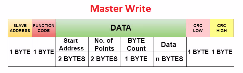
- Here the DATA field consists of the start address, the coil address where the modification begins
- The no of points, the number of coils master wants to modify
- The Byte count, the number of bytes master will be sending
- The DATA itself (for the coils)
The number of points and Byte count are different. Here in case of coils, the size of data for each coil is 1 Bit. We also know that the data can be only transferred in bytes.
So if the master wants to write upto 8 coils, it needs to send 1 byte of data. Similarly if the master wants to write upto 16 coils it needs to send 2 Bytes of data.
Even if the master wants to write 9 coils, it still need to send 2 bytes of data for the same.
2. Firmware Implementation:
In master project, open modbus.h header file.
Within the header, in modbusTypedefStruct, within the data structure, declare the following the element:
uint8_t Byte_Count;
Hence, the updated modbusTypedefStruct is as follows:
typedef struct
{
	uint8_t Slave_Address;
	uint8_t Function_Code;
	uint16_t Register_Address;
	uint16_t Number_of_Data;
	uint8_t  Byte_Count;

}modbusTypedefStruct;
Furthermore, declare the following define statement to handle single and multiple write request as follows:
#define SingleWrite 0x06
#define MultiWrite  0x10
Next, declare the following function:
void Modbus_WriteRequest(modbusTypedefStruct *ModbusFrame, uint8_t *data);
This function shall send the modbus frame over RS485 bus.
Hence, the updated header file:
#ifndef INC_MODBUS_H_
#define INC_MODBUS_H_

#include "main.h"

#include "stdint.h"

#define SingleWrite 0x06
#define MultiWrite  0x10


typedef struct
{
	uint8_t Slave_Address;
	uint8_t Function_Code;
	uint16_t Register_Address;
	uint16_t Number_of_Data;
	uint8_t  Byte_Count;

}modbusTypedefStruct;

void Modbus_ReadRequest(modbusTypedefStruct * ModbusFrame);

void Modbus_WriteRequest(modbusTypedefStruct *ModbusFrame, uint8_t *data);

#endif /* INC_MODBUS_H_ */
Next, open Modbus.c source file.
Within the source file, declare the following function:
void Modbus_WriteRequest(modbusTypedefStruct *ModbusFrame, uint8_t *data)
Within the function:
Extract the needed informations such as:
- Address
- Function code.
- Register address.
- Number of data.
uint8_t address = ModbusFrame->Slave_Address;
uint8_t func    = ModbusFrame->Function_Code;
uint16_t regAdd = ModbusFrame->Register_Address;
uint16_t numData = ModbusFrame->Number_of_Data;
Next, calculate byte counts as follows:
uint8_t byteCount = numData * 2;
Assuming the register can hold 2 bytes of data, hence the byte count shall be number of data*2.
Create a buffer to hold the data to be transmitted as follows:
uint8_t buffer[9 + byteCount];
Fill the buffer as shown in image in section 1 of this guide as follows:
buffer[0] = address;
buffer[1] = func;
buffer[2] = (regAdd >> 8) & 0xFF;
buffer[3] = (regAdd) & 0xFF;
buffer[4] = (numData >> 8) & 0xFF;
buffer[5] = (numData) & 0xFF;
buffer[6] = byteCount;
Copy the payload to the buffer as follows:
// Copy payload (external data buffer)
for (int i = 0; i < byteCount; i++)
{
  buffer[7 + i] = data[i];
}
Calculate the CRC value:
// CRC calculation
uint16_t crc = crc16(buffer, 7 + byteCount);
Fill the buffer with the CRC value as follows:
buffer[7 + byteCount] = crc & 0xFF;          // CRC Low
buffer[8 + byteCount] = (crc >> 8) & 0xFF;   // CRC High
Finally, send the data over RS485:
// Enable RS-485 TX
HAL_GPIO_WritePin(GPIOA, GPIO_PIN_0, GPIO_PIN_SET);

// Transmit frame
HAL_UART_Transmit(&huart1, buffer, 9 + byteCount, 100);

// Enable RS-485 RX
HAL_GPIO_WritePin(GPIOA, GPIO_PIN_0, GPIO_PIN_RESET);
Hence, the function as follows:
void Modbus_WriteRequest(modbusTypedefStruct *ModbusFrame, uint8_t *data)
{
    uint8_t address = ModbusFrame->Slave_Address;
    uint8_t func    = ModbusFrame->Function_Code;
    uint16_t regAdd = ModbusFrame->Register_Address;
    uint16_t numData = ModbusFrame->Number_of_Data;

    uint8_t byteCount = numData * 2;

    uint8_t buffer[9 + byteCount];

    buffer[0] = address;
    buffer[1] = func;
    buffer[2] = (regAdd >> 8) & 0xFF;
    buffer[3] = (regAdd) & 0xFF;
    buffer[4] = (numData >> 8) & 0xFF;
    buffer[5] = (numData) & 0xFF;
    buffer[6] = byteCount;

    // Copy payload (external data buffer)
    for (int i = 0; i < byteCount; i++)
    {
        buffer[7 + i] = data[i];
    }

    // CRC calculation
    uint16_t crc = crc16(buffer, 7 + byteCount);

    buffer[7 + byteCount] = crc & 0xFF;          // CRC Low
    buffer[8 + byteCount] = (crc >> 8) & 0xFF;   // CRC High

    // Enable RS-485 TX
    HAL_GPIO_WritePin(GPIOA, GPIO_PIN_0, GPIO_PIN_SET);

    // Transmit frame
    HAL_UART_Transmit(&huart1, buffer, 9 + byteCount, 100);

    // Enable RS-485 RX
    HAL_GPIO_WritePin(GPIOA, GPIO_PIN_0, GPIO_PIN_RESET);
}
Next, open main.c of the master project.
In user code begin PV, declare the following array which will hold the data to be transmitted as follows:
uint8_t TxBuffer[BufferSize];
In user code begin 3 in the while 1 function:
Send data to multiple registers as follows:
DataFrame.Slave_Address   = 0x11;
DataFrame.Function_Code   = MultiWrite;
DataFrame.Register_Address = 0x0001;
DataFrame.Number_of_Data   = 2;

TxBuffer[0] = random()%255;  // Register 0x0001 High
TxBuffer[1] = random()%255;  // 100

TxBuffer[2] = random()%255;  // Register 0x0002 High
TxBuffer[3] = random()%255;  // 200

Modbus_WriteRequest(&DataFrame, TxBuffer);

HAL_Delay(1000);
Currently, we are sending random data.
For writing single register:
DataFrame.Slave_Address   = 0x11;
DataFrame.Function_Code   = SingleWrite;
DataFrame.Register_Address = 0x0001;
DataFrame.Number_of_Data   = 1;


TxBuffer[0] = random()%255;  // Register 0x0001 High
TxBuffer[1] = random()%255;  // 100

Modbus_WriteRequest(&DataFrame, TxBuffer);

HAL_Delay(1000);
Thats all for the master firmware.
Save, build and run the project as follows:

3. Results:
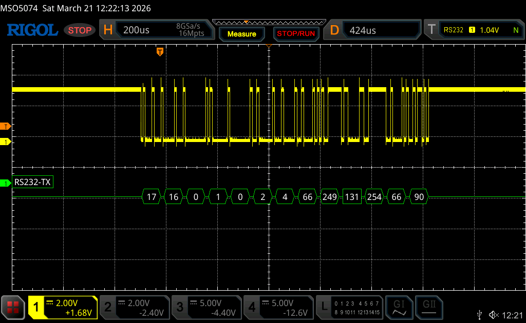
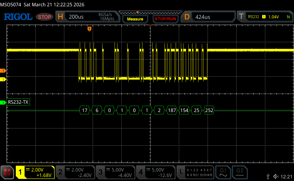
By using either oscilloscope or logic analyzer, probe the TX line of the UART and you should get the following:
For multiple register write:
For single register write:
Thats all for this guide.
In next part, we shall develop the firmware for the slave to store the register data send by the master.
Stay tuned.
Happy coding 😉
Add Comment