Part 1 introduces the STM32F429-Discovery board, covering its onboard resources, including the integrated display, and guides you through setting up the development environment using STM32CubeMX and importing the project into STM32CubeIDE. It also walks through analyzing the schematic to identify the MCU pin mappings, establishing a clear foundation for subsequent hardware and software integration.
In this guide, we shall cover the following:
- Introduction.
- Getting the required pins from schematic.
- STM32CubeMX setup.
- Importing project to STM32CubeIDE.
1. Introduction:
The STM32F429 Discovery board is a comprehensive development platform built around the high-performance STM32F429ZI microcontroller from STMicroelectronics, designed to provide engineers with immediate access to advanced embedded graphics, DSP, and real-time control capabilities. At its core, the STM32F429 MCU features an ARM Cortex-M4 core with FPU, operating at up to 180 MHz, enabling efficient execution of both control-oriented firmware and computationally intensive tasks such as signal processing and graphical rendering. The board integrates a rich set of peripherals including multiple SPI, I2C, USART, CAN, and SDIO interfaces, along with advanced timers and ADCs, making it highly suitable for complex embedded systems development. One of its defining characteristics is the inclusion of an LTDC (LCD-TFT Display Controller) and DMA2D (Chrom-ART Accelerator), which significantly offload graphics operations from the CPU, enabling smooth UI rendering and high frame rates—critical for modern human-machine interface (HMI) applications.
In addition to processing and graphics capabilities, the STM32F429 Discovery board provides a well-rounded hardware ecosystem that includes an onboard ST-LINK/V2 debugger/programmer, eliminating the need for external debugging tools and allowing seamless integration with development environments such as STM32CubeIDE. The board also features external SDRAM, which is essential for framebuffer storage when working with graphical displays, as well as MEMS sensors, audio DAC, user input buttons, and LEDs for rapid prototyping. This combination of onboard resources allows developers to move quickly from concept to implementation without requiring extensive external circuitry. The hardware design is fully documented, and the availability of schematics enables engineers to trace signal paths, understand pin multiplexing, and optimize peripheral usage—an essential step when working with display interfaces and ensuring correct configuration of GPIOs, alternate functions, and communication buses.
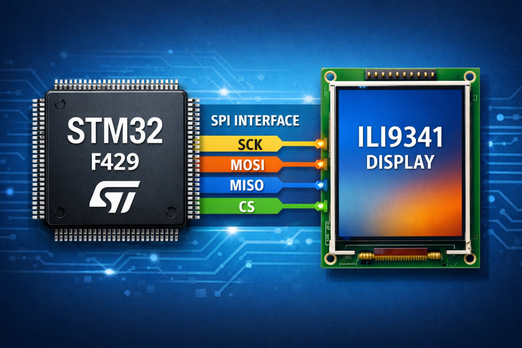
A key highlight of the STM32F429 Discovery board is its integrated TFT display, driven by the ILI9341, which is a widely adopted display controller in embedded systems due to its balance between performance, simplicity, and flexibility. The ILI9341 is a 240×320 pixel (QVGA) TFT LCD controller capable of displaying 262K colors (18-bit color depth), delivering vibrant and sharp visuals suitable for embedded GUIs. It supports multiple communication interfaces, including SPI, parallel RGB, and MCU interfaces, allowing it to be used across a wide range of hardware configurations. In the context of this guide, the SPI interface is particularly important, as it provides a relatively simple and pin-efficient method of communication between the STM32 MCU and the display, albeit with some trade-offs in throughput compared to parallel interfaces.
From an architectural standpoint, the ILI9341 integrates its own GRAM (Graphics RAM), enabling the host MCU to write pixel data directly to the display memory without needing to continuously refresh the screen. This significantly reduces bandwidth requirements and simplifies rendering logic. The controller also includes a rich command set for display control, including orientation configuration, pixel format selection, gamma correction, frame rate control, and power management, giving developers fine-grained control over display behavior and visual output. Furthermore, it supports hardware scrolling, partial display modes, and sleep modes, which are useful for optimizing both performance and power consumption in embedded applications.
Electrically, the ILI9341 operates at standard logic levels compatible with most microcontrollers, and its SPI interface typically utilizes signals such as SCK (clock), MOSI (data input), MISO (optional data output), CS (chip select), D/C (data/command selection), and RESET, all of which must be correctly mapped to the STM32F429 GPIO pins as defined in the board schematic. Understanding this mapping is critical, as incorrect configuration can lead to communication failures or improper display behavior. Additionally, timing constraints and SPI configuration parameters—such as clock polarity, phase, and baud rate—must be aligned with the ILI9341 specifications to ensure reliable data transfer.
From a software perspective, driving the ILI9341 over SPI involves initializing the display through a defined sequence of commands, followed by sending pixel data in the correct format. While SPI introduces some bandwidth limitations compared to the STM32F429’s native LTDC interface, it remains a popular choice for its simplicity and reduced pin count, especially in applications where ultra-high frame rates are not required. With proper optimization techniques—such as DMA-driven SPI transfers and efficient buffering strategies—developers can still achieve responsive and visually appealing interfaces.
In summary, the STM32F429 Discovery board provides a powerful and flexible platform for embedded graphics development, combining a high-performance MCU, dedicated graphics acceleration hardware, and extensive onboard resources. Complementing this is the ILI9341 display controller, which offers a robust and feature-rich solution for driving TFT displays over SPI, with capabilities that include full-color rendering, internal frame memory, flexible interface options, and advanced display control features. Together, they form an ideal foundation for developing sophisticated embedded GUI applications, where understanding both the hardware architecture and interface configuration is essential for achieving optimal performance and reliability.
2. Getting the Required Pins from Schematic:
Open STM32F429IDisovery webpage from here.
Next from CAD resources, Schematic Pack, download the proper version for your board. Mine is C01.
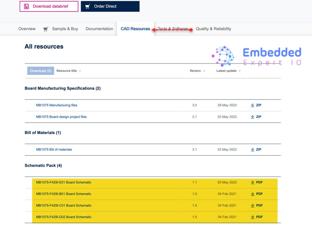
From the STM32F429-Disco shcematic, we can find as following:
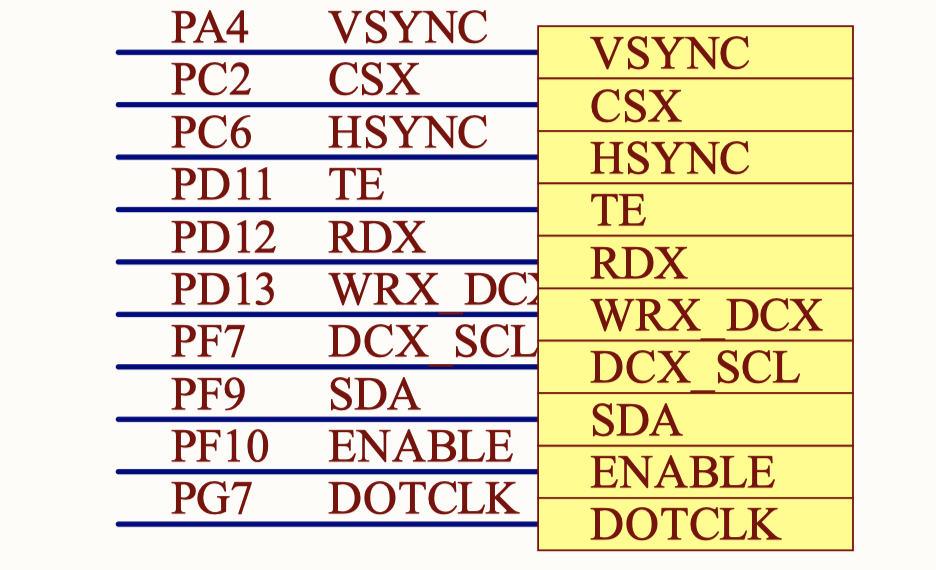
| STM32F429-disco | ILI9341 |
| PA7 | LCD RST |
| PC2 | LCD CS |
| PD13 | LCD DC |
| PF7 | SPI5 SCK (SCL) |
| PF9 | SPI5 MOSI (SDA) |
Keep those pins in your mind.
3. STM32CubeMX Setup:
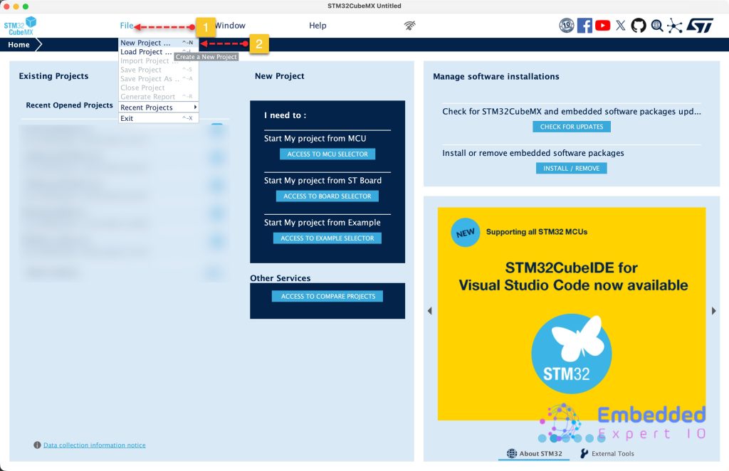
Open STM32CubeMX and start new project as follows:
Next, type F429Zi which is the chip onboard of STM32F429 discover board.
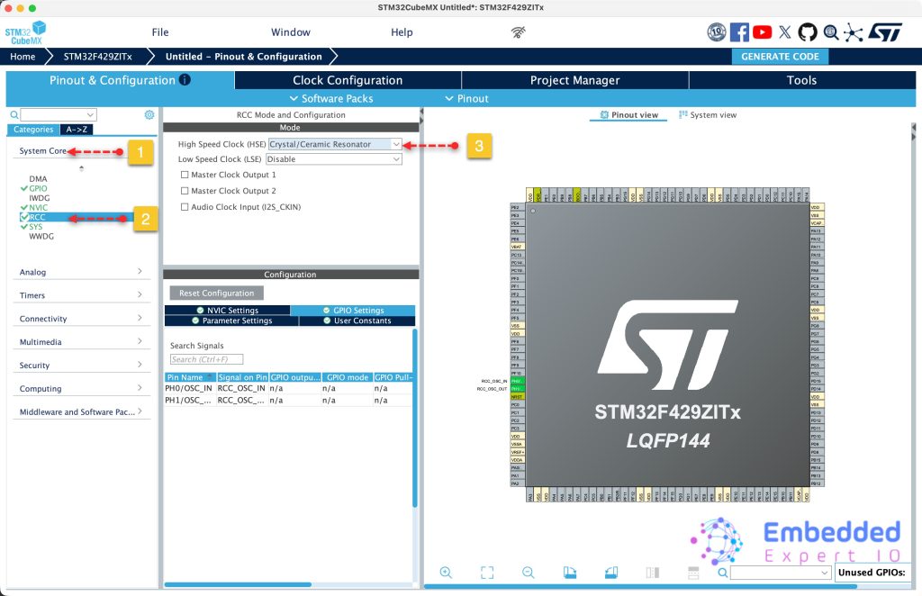
From System Core, RCC enable the crystal oscillator as follows:
Next, from Clock Configuration tab:
- Set Clock frequency to 8.
- PLL source to HSE.
- Set HCLK to 180
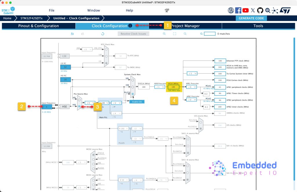
With these settings, you should get the maximum speed to the MCU.
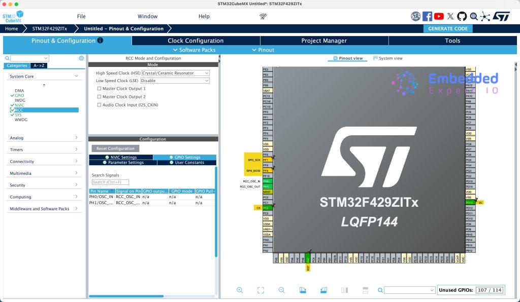
Next, from Pinout and configuration, set the following pins:
- PA7 as output and name it RST.
- PC2 as output and name it CS
- PD13 as output and name it DC.
- Set PF7 and PF9 for SPI5 SCK and SPI5 MOSI respectively.
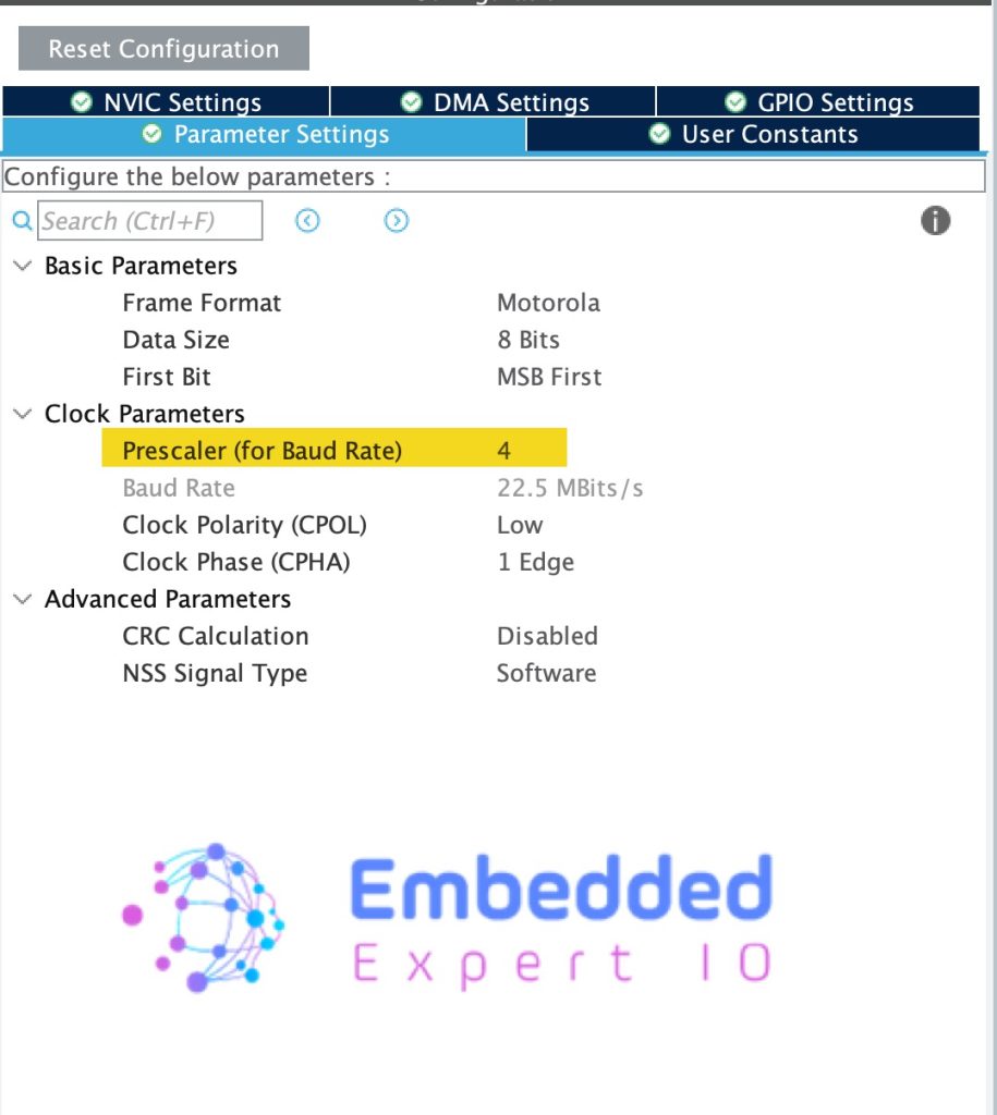
Next, from Connectivity, select SPI5 and enable it in half-duplex master mode as follows:
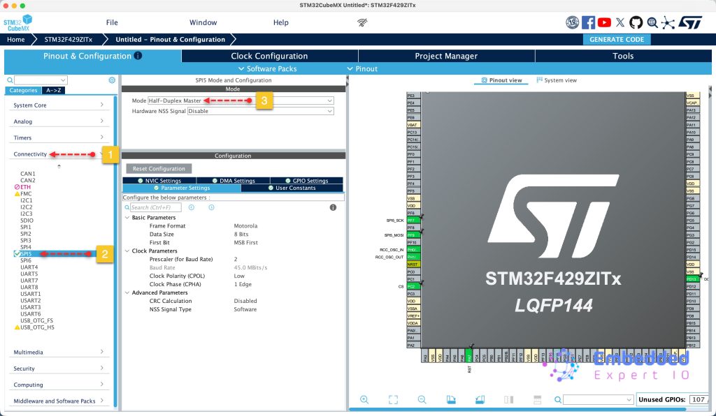
From parameter settings, set the prescaller to 4 to provide 22.5Mbps and keep the rest as is as follows:
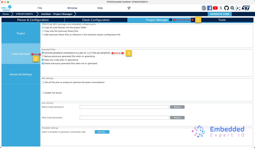
Next, from project tab, select code generation and enable generate peripherals initialization as pair of .c/.h files as follows:
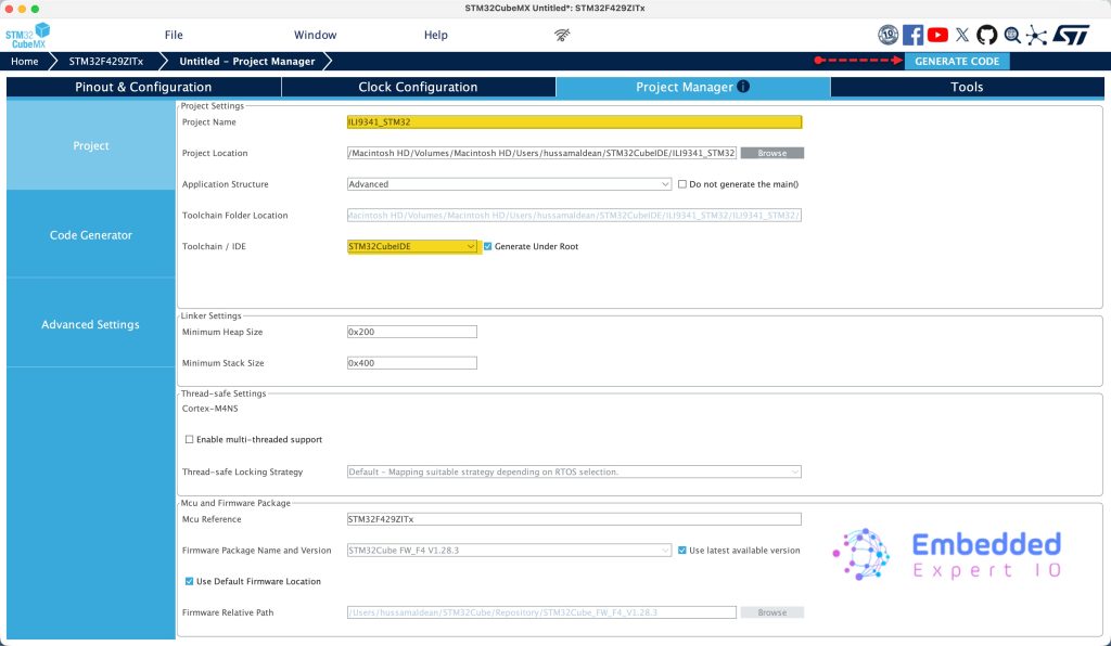
Finally from project, set the destination, give the project a name and set toolchain/IDE to STM32CubeIDE and click on Generate Code as follows:
4. Importing Project to STM32CubeIDE :
Open STM32CubeIDE, select your workspace and click on Launch.
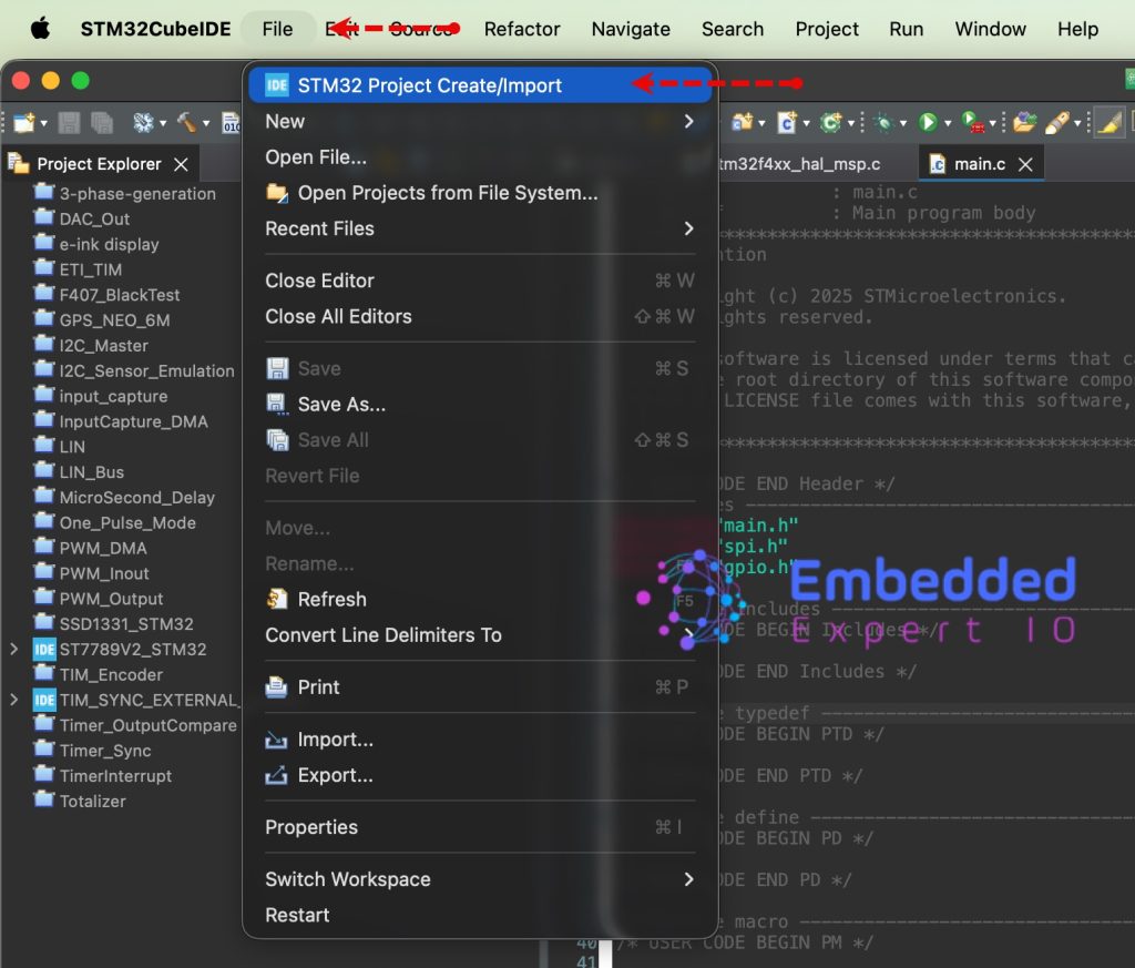
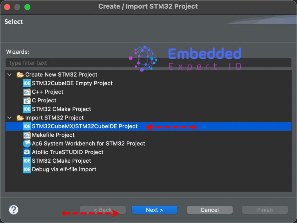
From the IDE, click File and select STM32 Project Create/Import as follows:
Next, from Import STM32 Project, select STM32CubeMX/STM32CubeIDE Project and click on Next as follows:
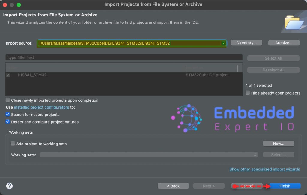
Next, select the folder that contains the .ioc file and click on Finish as follows:
Thats all for part 1.
Stay tuned for part 2 where we shall initialize the LCD and draw random colors to each pixel of the display.
Happy coding 😉
Add Comment