Part 1 introduces RS-485 as a robust, differential serial communication standard widely used in industrial and embedded systems for its noise immunity and long-distance capability.
In this part, we focus on STM32 HAL configuration and the fundamentals of transmitting data over an RS-485 interface.
In this guide, we shall cover the following:
- Introduction.
- Hardware setup
- STM32CubeMX setup.
- Importing project to STM32CubeIDE.
- Firmware development.
- Results.
1. Introduction:
RS-485, also known as TIA-485 or EIA-485, is a standard introduced in 1983. It defines the electrical characteristics of drivers and receivers for use in serial communication systems. Here are some key points about RS-485:
- Balanced Signaling: RS-485 uses balanced electrical signaling over twisted pair cables. This makes it robust against noise and interference, making it suitable for industrial environments.
- Multipoint Communication: RS-485 supports multipoint systems, allowing multiple devices to communicate over long distances using a single twisted pair of wires. It’s commonly used in industrial control systems.
- Data Rates and Distances: RS-485 can handle data rates up to 10 Mbit/s (or lower speeds) and distances up to 1,200 meters (4,000 feet).
- Three-State Logic: Unlike RS-422, RS-485 drivers use three-state logic, allowing individual transmitters to be deactivated. This enables linear bus topologies using only two wires.
Remember, RS-485 is a reliable choice for connecting devices in noisy environments or over extended distances.
RS485 is used in many computer and automation systems. Some of the examples are robotics, base stations, motor drives, video surveillance and also home appliances. In computer systems, RS485 is used for data transmission between the controller and a disk drive. Commercial aircraft cabins also use RS485 for low-speed data communications. This is due to the minimal wiring required due to the wiring configuration requirements of RS485.
RS485 is however most popularly used in programmable logic controllers and factory floors where there are lots of electrical noise. RS485 is used as the physical layer for many standards and proprietary automation protocols to implement control systems, most commonly Modbus.
Modbus is the world’s most popular automation protocol in the market. Developed by Modicon, Modbus enables different devices from different manufacturers to be integrated into the main system. Most Modbus implementations use RS485 due to the allowance of longer distances, higher speeds and multiple devices on a single network.
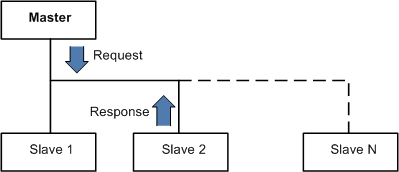
Modbus devices communicate using a Master-Slave technique where only one device (the Master) can initiate transactions (AKA queries). The other devices (the slaves) respond by giving the requested data to the master, or by taking the action requested in the query. This whole system allows manufacturing facilities to control their devices remotely and also set-up automation.
How RS485 works?

Ref: lammertbies
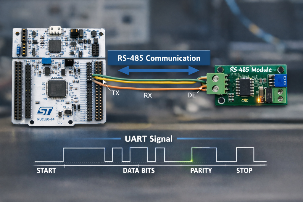
In RS485 standard, data is transmitted via two wires twisted together also referred to as “Twisted Pair Cable”. The twisted pairs in RS485 give immunity against electrical noise, making RS485 viable in electrically noisy environments.
RS485 at its core with 2 wires allows half-duplex data transmission. This means data can be transmitted in both directions to and fro devices one direction at a time. By adding another 2 wires, making it a 4 wires system, it allows data transmission in both directions to and fro devices at the same time, also known as full-duplex. However, in a full-duplex setup, they are limited to a master and slave communication where slaves cannot communicate with each other.
The signal level used during the RS485 communication method typically ranges from -7V to +12V. The microcontroller pins are generally not designed to handle these levels. This is why these signals needs to be converted to low voltages, for eg ±3V. The module have the MAX485 chip on it, which does most of the job of conversion.
The pinout of the module is shown below
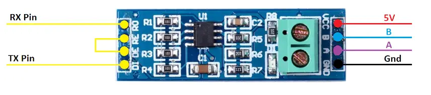
On the left side of the module, the RO pin connects to the RX pin of the UART, and the DI pin connects to the TX pin.
The RE and DE Pins are responsible for setting the module in Receiver or Transmitter mode.
- When the RE pin is LOW and DE pin is LOW, the Module is set in the Receiver mode.
- When the DE pin is HIGH and RE pin is HIGH, the Module is set in the Transmitter mode.
The Pin A and the Pin B are the output pins which carries the transmission signal.
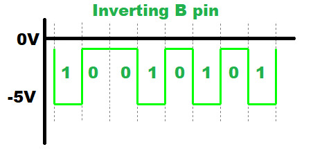
Let’s take an example where we provide the data, 0x95 (10010101) to the module. If the Module is powered with 5V, the output on pins A and B will be as shown below
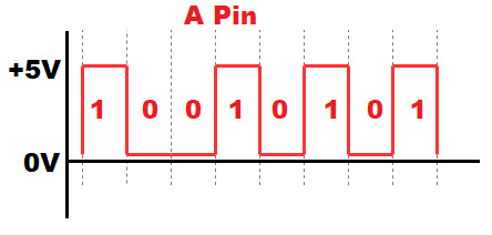
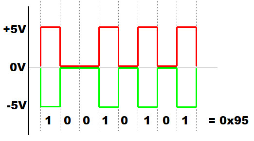
- Since A is the non-inverting pin, it’s output will be in sync to the input. It varies between 0 to +5V
- B is the inverting pin, so the output is inverted and varies between -5V to 0
- When the second module receives these as inputs, it decode the data based on the voltage differences.
- If the voltage difference is maximum, the bit is 1, and if the difference is 0 the bit is 0
- This data is then converted to lower voltages (0 to 3V) to suit the MCU requirement.
2. Hardware Setup:
The hardware setup as follows:
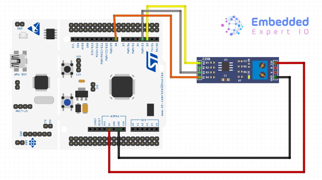
As shown above, The RO pin is connected to the PA10 (UART1 RX) and DI pin is connected to the PA9 (UART1 TX).
The RE and DE are connected together with the pin PB3 of the MCU.
3. STM32CubeMX Setup:
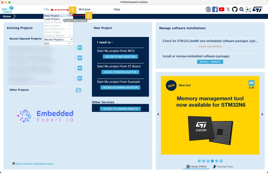
Open STM32CubeMX as start a new project as follows:
Search for your STM32 MCU, select the MCU and click on Start New Project as follows:

This guide will use STM32L476RG Nucleo-64 board development platform.
Next, once the project has started, select connectivity, then USART1. Set the mode to Asynchronous mode, enable hardware flow control for RS485.
Please note that not all STM32 MCUs have the flow control for RS485
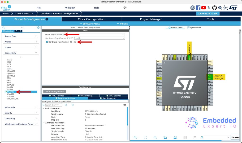
This will configure PA9 and PA10 as USART1_TX and USART1_RX respectively. Also, you set PB3 as the DE signal of RS485 or keep the default one.
Leave the parameters as is. No need to change anything here.
Next from Project Manager tab, give the project a name, set the toolchain/IDE to STM32CubeIDE and click on Generate Code as follows:

That all for the STM32CubeMX setup.
4. Importing Project to STM32CubeIDE.
Open STM32CubeIDE, select your workspace and click on Launch.
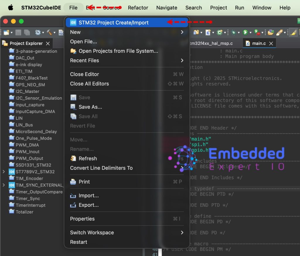
From the IDE, click File and select STM32 Project Create/Import as follows:
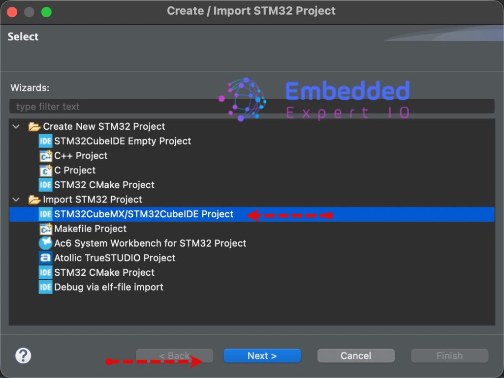
Next, from Import STM32 Project, select STM32CubeMX/STM32CubeIDE Project and click on Next as follows:
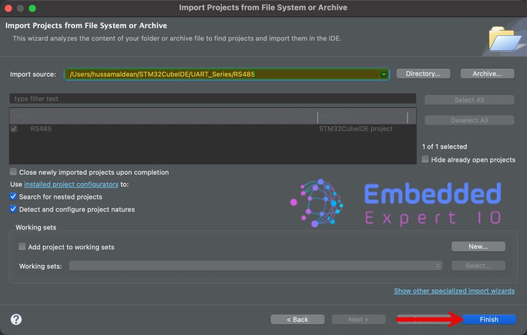
Next, select the folder that contains the .ioc file and click on Finish as follows:
Now, the project is the project window.
5. Firmware Development:
Open main.c file for the project.
In user code begin includes, include the stdio header file as follows:
#include "stdio.h"
Next, in user code begin PV, declare the following two variables:
uint8_t counter;

char buffer[40];
- counter which will hold the counted value.
- buffer which will hold the data to be transmitted over RS485.
Next, in user code begin 3 in while 1 loop:
uint16_t len=sprintf(buffer,"Counter = %d\r\n",++counter);

HAL_UART_Transmit(&huart1, buffer, len, 100);

HAL_Delay(100);
First, using sprintf, we shall construct character array to hold the string to be send.
Then, send the data over the UART.
Wait for 100ms before sending the next data.
Save, build and run the project as follows:

6. Results:
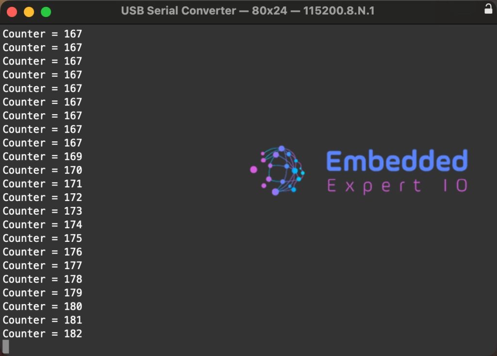
By using RS485-USB converter, you should see the following:
Open serial terminal and set the baudrate to 115200.
By probing the Tx pin and DE/RE pin:
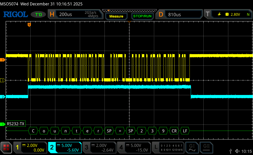
Not that the DE/RE pin is high during the transmission process and remains low the rest of the time to ensure the receiver will be able to receive the data.
In next part, we shall receive data over RS485.
Stay tuned.
Happy coding 😉
Add Comment