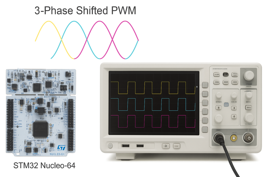
Timer synchronization for three-phase PWM generation allows multiple timers to operate with precise phase shifts, typically 120° apart, to produce accurately timed PWM outputs. This phase-shifted synchronization is crucial in applications like three-phase motor drives and inverters, where consistent phase relationships ensure smooth rotation and balanced power delivery.
In this guide, we shall cover the following:
- Introduction.
- STM32CubeIDE Setup.
- Firmware Development.
1. Introduction:
In motor control and power electronics, generating precise and synchronized Pulse Width Modulation (PWM) signals is a fundamental requirement for driving three-phase motors such as Brushless DC (BLDC) or Permanent Magnet Synchronous Motors (PMSM). These applications demand not only accurate frequency and duty cycle control but also precise phase alignment between the three PWM signals—typically spaced by 120° electrical degrees. Achieving this synchronization ensures smooth motor rotation, minimizes torque ripple, and enhances system efficiency and performance.
Timer synchronization in STM32 microcontrollers allows multiple timers to operate in a coordinated manner where one timer (the master) controls the start, update, or reset events of other timers (the slaves). This feature is critical when generating three-phase PWM signals because it guarantees that each timer starts counting at a defined offset, maintaining exact phase relationships between channels. For instance, in a three-phase inverter control system, Timer 1 can act as the master timer generating Phase A, while Timer 2 and Timer 3 are configured as slave timers producing Phases B and C, each shifted by 120° relative to the master.
By using trigger mode in timer synchronization, the master timer generates synchronization pulses that trigger or reset the slave timers, ensuring all timers operate on a unified time base. This eliminates timing drift caused by independent timer clock domains or interrupt latencies, which could otherwise distort phase relationships and cause imbalance in motor currents. The synchronization can be achieved through internal trigger connections (ITRx lines), allowing timers to exchange synchronization signals internally without using external pins.
This method of generating phase-shifted PWM signals is not only crucial for motor control but also valuable in power converters, multilevel inverters, and interleaved DC-DC converters. It ensures consistent waveform generation, balanced load distribution, and precise control over switching events—key factors in achieving high performance and reliability in embedded power systems. In short, timer synchronization with phase-shifted PWM is one of the most efficient hardware-level techniques to achieve deterministic, real-time control for advanced embedded applications.
2. STM32CubeIDE Setup:
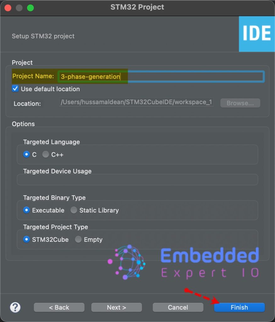
Open STM32CubeIDE after selecting the workspace and create new project as following:

Select the MCU:

Give the project a name:
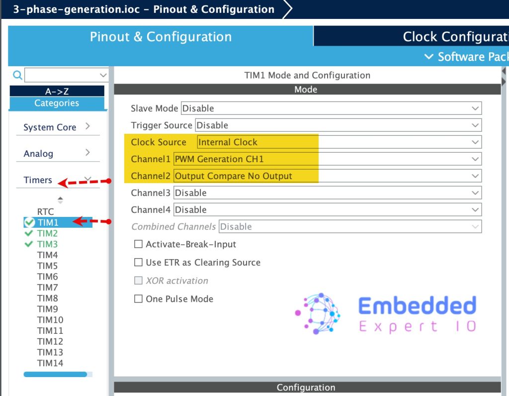
Next, Enable TIM1 since it will be the master as follows:
- Set the clock source to internal clock.
- Set Channel 1 as PWM CH1.
- Set Channel 2 as Output Compare No Output.
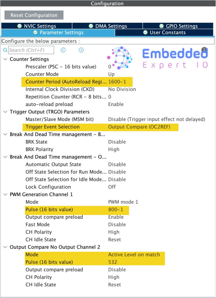
Next, in parameter configuration:
- Set the counter period to 1600-1.
- Trigger Event Selection to Output Compare (OC2REF) since we set CH2 as output compare.
- For PWM Generation, set the pulse to 800-1, this will give us 50% duty cycle.
- For output Compare, set the mode to Active level on match and pulse to 532.
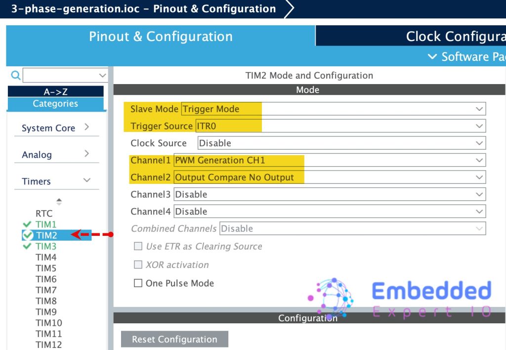
Next, enable the TIM2 as follows:
- Set slave mode to trigger mode.
- Trigger Source to ITR0 since it will be triggered by TIM1.
- Set CH1 to PWM and CH2 to output compare no output.
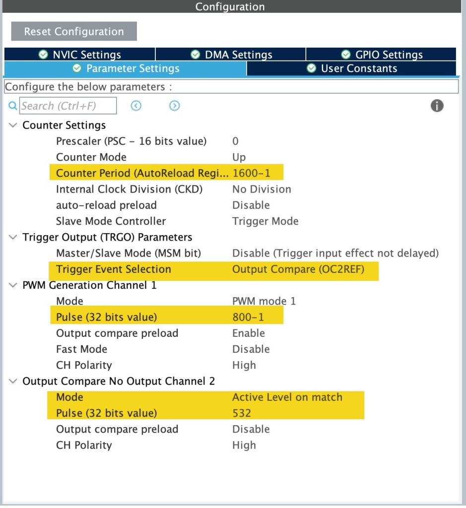
Next, configure timer as follows:
- Counter Period to 1600-1.
- Trigger event selection to output compare (OC2REF)
- For PWM Channel, set the pulse to 800-1, this will give us 50% duty cycle.
- For output compare channel, set the mode to Active Level on Match and Pulse to 532.
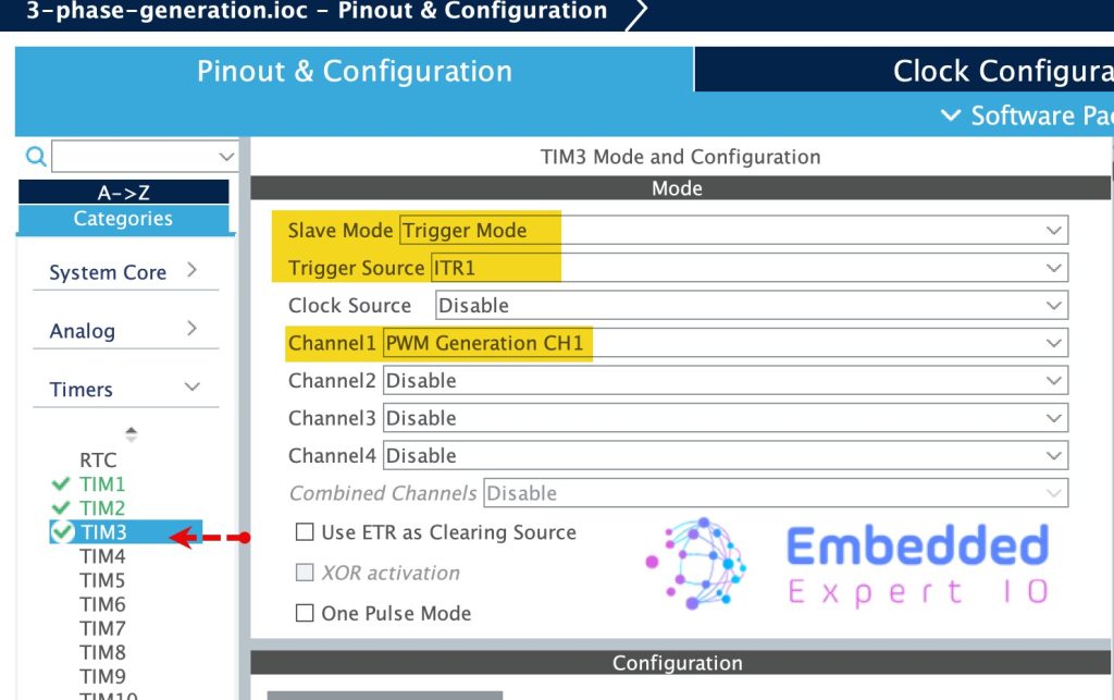
For TIM3, Enable it as follows:
- Slave Mode to Trigger Mode.
- Trigger source to ITR1 (Triggered by TIM2).
- Set Channel 1 to PWM Generation.
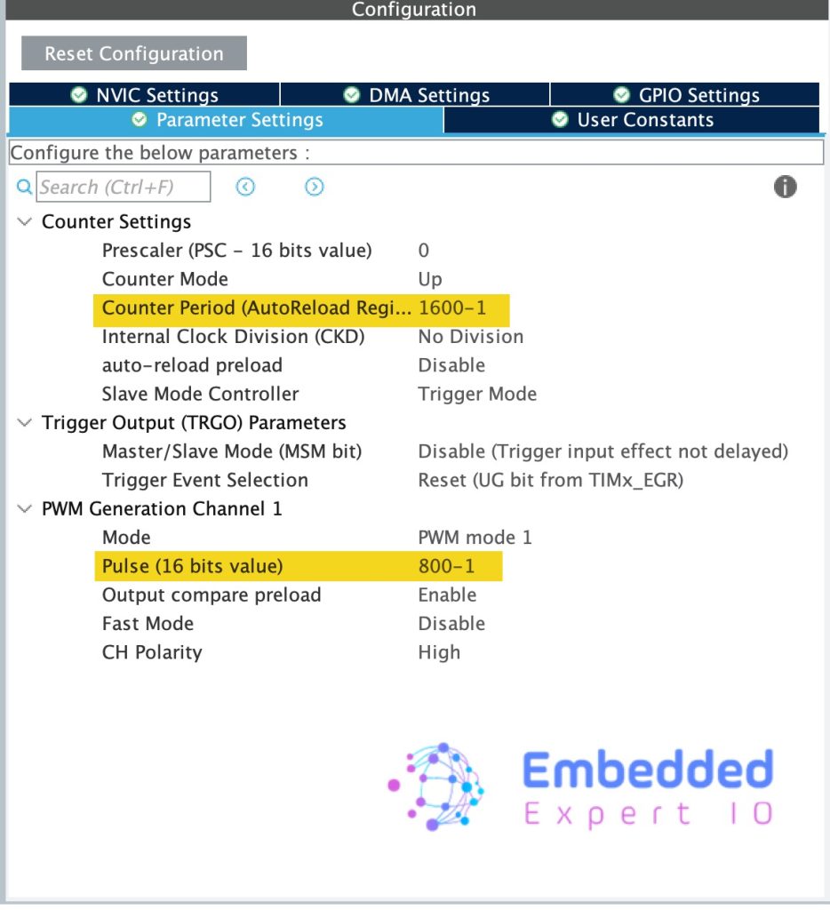
For TIM3 configuration:
- Set counter period to 1600-1.
- Set pulse of PWM to 800-1.
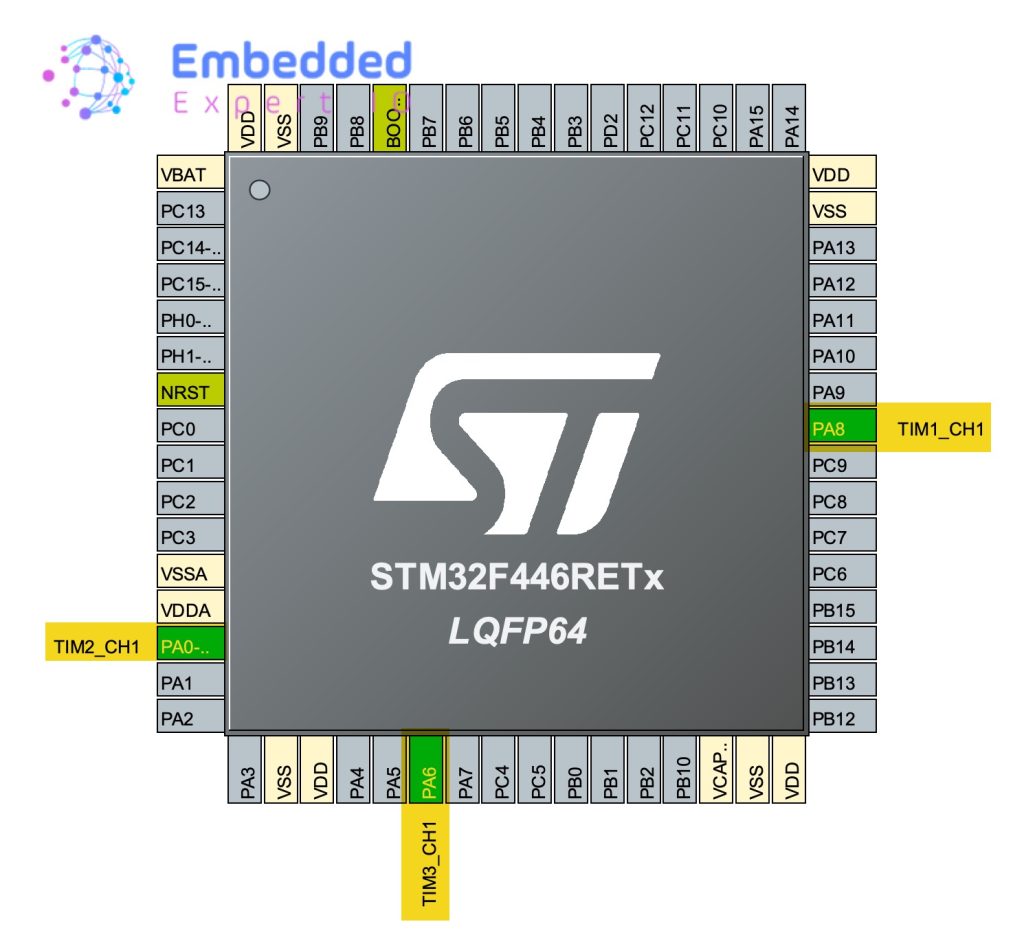
With those configuration, the following pins will be enabled:
- PA8 for TIM1_CH1.
- PA0 for TIM2_CH1.
- PA6 for TIM3_CH1.
That all for the configuration. Save the project and this will generate the code.
3. Firmware Development:
Once the code has been generated, main.c shall be opened.
In main.c in user code begin 2 in main function, start TIM3 as follows:
HAL_TIM_PWM_Start(&htim3, TIM_CHANNEL_1);
Since TIM3 has only PWM, we only need to start the PWM channel.
For TIM2:
HAL_TIM_PWM_Start(&htim2, TIM_CHANNEL_1);
HAL_TIM_OC_Start(&htim2, TIM_CHANNEL_2);
For TIM2, we need to start CH1 as PWM and CH2 as Output Compare.
For TIM1:
HAL_TIM_PWM_Start(&htim1, TIM_CHANNEL_1);
HAL_TIM_OC_Start(&htim1, TIM_CHANNEL_2);
Similar to TIM2.
That all for the firmware. Save, build and run the project.
4. Results:
By using either logic analyzer or oscilloscope, probe PA8, PA0 and PA6, you should get the following:
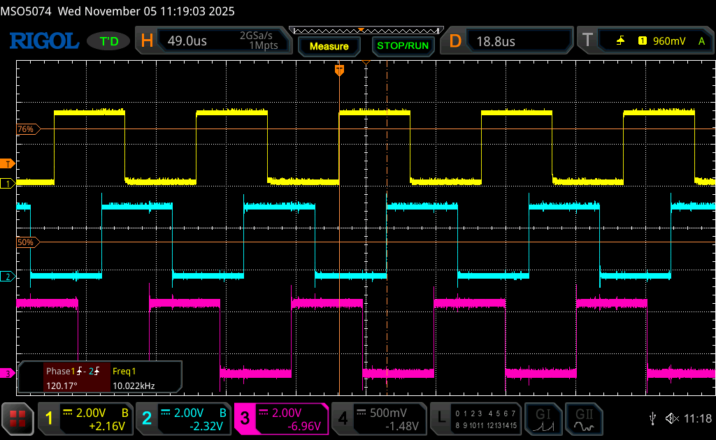
Note that the frequency is 10KHz and we set the period (16000000/1600)=10,000 and the phase difference is 120 degree and intended.
Now, we have the basic of PWM generation for three phase.
Happy coding 😉
Add Comment