In this guide, we shall cover how to transmit and receive data from a slave device connected to out STM32H5. The slave device is ADXL345 accelerometer.
In this guide, we shall cover the following:
- Configure SPI for ADXL345.
- ADXL345 connection.
- Modification to the library.
- Results.
1. Configure the SPI for ADXL345:
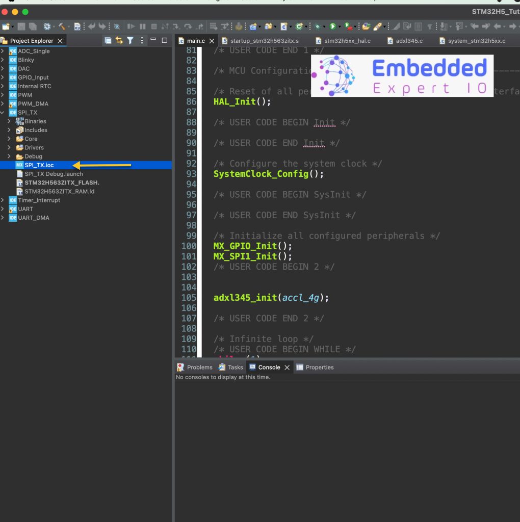
Open SPI_TX.ioc file as following:
From connectivity, select the SPI and configure it as following:
Keep the baudrate as it since it will work just fine.
Set the following:
- Clock Polarity (CPOL) to High.
- Clock Phase (CPHA) tp 2 Edge.
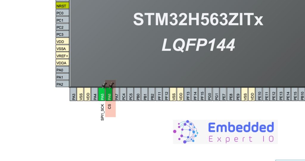
From the pins, give PA6 a name as CS as following:
Save the project and this will generate the project again.
2. ADXL345 Connection:
The sensor shall be connected as following:
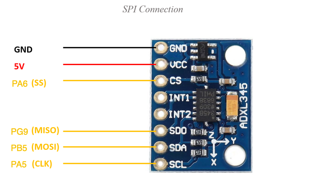
| ADXL345 | STM32H563ZI-Nucleo144 |
| Vcc | 5V |
| GND | GND |
| CS | PA6 (Arduini pin A0) |
| SDO | PG9 (Arduino pin D12) |
| SDA | PB5 (Arduino pin D11) |
| SCL | PA5 (Arduino pin D13) |
3. Modification to the Library:
Next, head to this guide here or simply, download the entire code from here:
in ADXL345.c source file, include the main.h as following:
#include "main.h"
For CS line, read and write to the sensor functions:
static void cs_enable()
{
	HAL_GPIO_WritePin(CS_GPIO_Port, CS_Pin, 0);
}

static void cs_disable()
{
	HAL_GPIO_WritePin(CS_GPIO_Port, CS_Pin, 1);
}


static void adxl345_write(uint8_t address, uint8_t value)
{
	uint8_t data[2];

	/*Enable multi-byte, place address into buffer*/
	data[0] = address|MULTI_BYTE_EN;

	/*Place data into buffer*/
	data[1] = value;

	/*Pull cs line low to enable slave*/
	cs_enable();

	/*Transmit data and address*/

	HAL_SPI_Transmit(&hspi1, data, 2, 100);


	/*Pull cs line high to disable slave*/
	cs_disable();


}

static void adxl345_read(uint8_t address, uint8_t * rxdata)
{

	/*Set read operation*/
	address |= READ_OPERATION;

	/*Enable multi-byte*/
	address |= MULTI_BYTE_EN;

	uint8_t DummyBuffer[6];

	DummyBuffer[0]=address;

	for (int i=1;i<5;i++)
	{
		DummyBuffer[i]=0xFF;
	}


	/*Pull cs line low to enable slave*/
	cs_enable();

	HAL_SPI_TransmitReceive(&hspi1, DummyBuffer, rxdata, 6, 300);

	/*Pull cs line high to disable slave*/
	cs_disable();

}
The rest of the code shall remain the same, except removing the following functions from the initialization function of the sensor:
adxl_spi_pins_init();
adxl_spi_config();
In main.c file:
first include the adxl library as following:
#include "adxl345.h"
Declare the acceleration data structure to handle the acceleration as following:
accleration_values_t accleration_values;
In the main function, initialize the sensor as following:
adxl345_init(accl_4g);
In the while loop, update the sensor values as following:
adxl345_update();
adxl345_get_values(&accleration_values);
Save the project, build it and run it on your STM32H563Zi board.

4. Results:
By probing the 4pins using oscilloscope or logic analyzer, we can find that we have successfully send 6 bytes of data and receive 6 bytes of data from the sensor.

Happy coding 😉
Add Comment