In previous two guides (part one and part 2) we looked at the ADC conversion using two methods, first one was single conversion and seconds was continuous conversion. The two methods proven to be effect in certain area. however, we have to wait for the end of conversion each time we want to read the adc which might effect the performance of the system (like in car).
In this guid will cover the following
- Difference between polling mode and interrupt mode
- Extra steps needed
- Needed Parts and Schematic
- Code
- Result
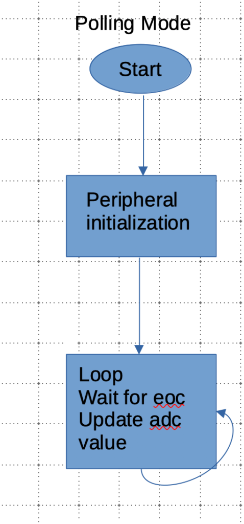
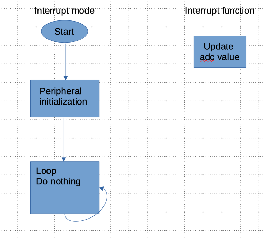
1. Difference between polling mode and interrupt mode
In polling as we saw in previous two guides, we need to wait for end of conversion each time we want to read the adc value as illustrated in figure below.
On another hand, in interrupt mode, the adc value can be update in background (no need to wait for EOC) since in handled in the interrupt handler function as illustrated in figure below.
2. Extra steps needed to enable interrupt.
The extras steps needed from part 1 and part 2 of this guid as following
- Declare the adc_value as volatile uint16_t variable as following
volatile uint16_t adc_value;
- Enable end of conversion interrupt from ADC_CR1 as shown bellow
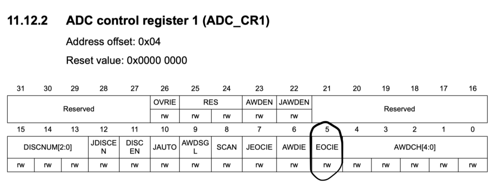
ADC1->CR1|=ADC_CR1_EOCIE;
- Attach the EOC to the NVIC (Nested Vector Interrupt Controller) by using the following command
NVIC_EnableIRQ(ADC_IRQn);
- Handle the ADC interrupt as follow
void ADC_IRQHandler(void)
{
adc_value=ADC1->DR;
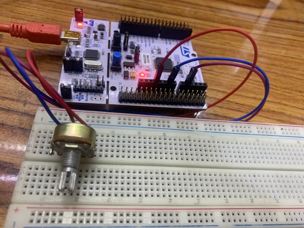
}3. Required Parts and Schematics
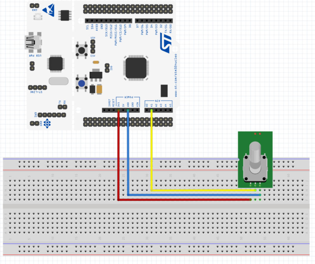
You will need the following parts:
- STM32F411 Nucleo-64
- BreadBoard
- 1KOhm Potentiometer
- Hookup wires (male-male)
We shall use Keil uVision (MDK-ARM) IDE (Link)
4. Code
//read the analog voltage on PA1
#include "stm32f4xx.h" // Device header
#include "stdint.h"
void ADC_init(void);
uint16_t adcValue;
int main(void){
ADC_init();
while(1){
//empty loop
}
}
void ADC_init(void){
RCC->AHB1ENR|=RCC_AHB1ENR_GPIOAEN; //enable gpio a clock
RCC->APB2ENR|=RCC_APB2ENR_ADC1EN; //enable adc clock
GPIOA->MODER|=GPIO_MODER_MODER1; //set the PA1 to analog mode
ADC1->CR1|=ADC_CR1_EOCIE;
ADC1->CR2=0; //disable the adc
ADC1->CR2|=ADC_CR2_CONT; //enable Continuous conversion
ADC1->SQR3|=1; //set the second channel to be converted first
NVIC_EnableIRQ(ADC_IRQn); //attach the interrupt to NVIC
ADC1->CR2|=1; //enable the adc
ADC1->CR2|=ADC_CR2_SWSTART; //start adc conversion
}
void ADC_IRQHandler(void)
{
//update adc vlaue automatically
adcValue=ADC1->DR;
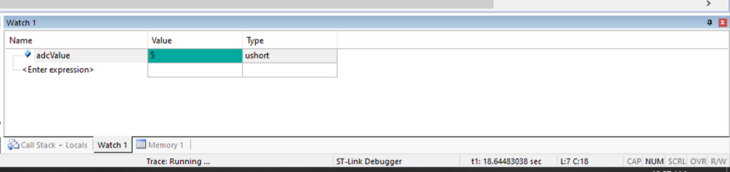
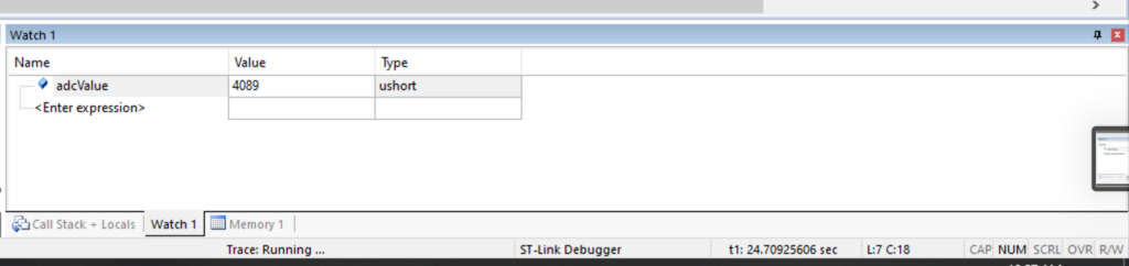
}5. Results
After compile, upload, start a debug session and adding adcValue to watch window.
Rotate the pot left and right and the value shall be updated without being called each time
Add Comment