In this revised guide, we shall see how interface GLCD 128×64 with STM32 using SPI method (Serial mode).
In this guide, we shall cover the following:
- GLCD 12864.
- Interface with STM32.
- Developing the driver.
- Code
- Demo.
1. GLCD 12864:
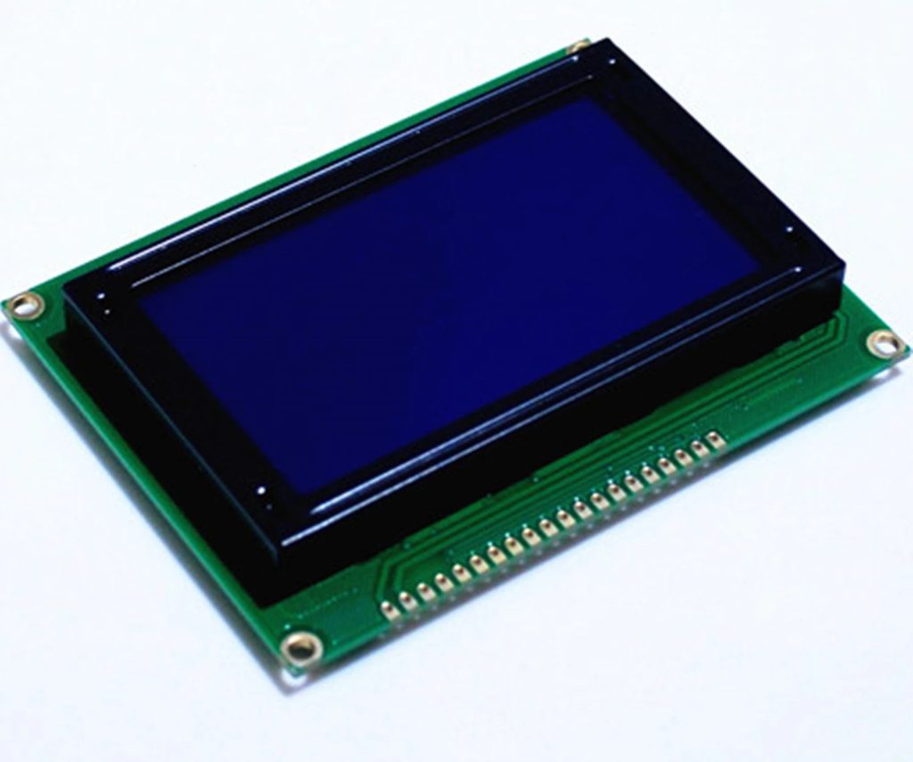
At first glance, the 128×64 Graphical LCD Module seems like a bigger brother to the famous 16×2 LCD or 20×4 LCD Modules, with their similar construction and almost similar pin layout.
But there is a significant difference between those two. 16×2 or 20×4 LCDs are essentially character displays. They can only display alpha-numeric characters and some simple custom characters that are confined to a 5×8 matrix.
Coming to the 128×64 Graphical LCD, as the name suggests, it is a Graphical Display consisting of 128×64 i.e., 8192 individually controllable dots.
By using different combinations of pixels, we can basically display characters of various sizes. But the magic doesn’t end there. You can display images and graphics (small animations) as well. In a 128×64 LCD Module, there are 64 rows and 128 columns.

ST7920 LCD Controller
There are several versions of the Graphical LCD in the market. Even though the usage, application and implementations are almost identical, the main difference lies in the internal LCD Controller used to drive the dot matrix display.
Some of the commonly used LCD Controllers are KS0108, SSD1306, ST7920, SH1106, SSD1322, etc. The pin out of the final LCD Module might vary depending on the LCD Controller used. So, please verify the LCD Controller as well as the pin out before making a purchase.
The Graphical LCD Module I purchased consists of ST7920 Controller. It is manufactured by Sitronix and supports three types of bus interfaces i.e., 8-bit mode, 4-bit mode and Serial interface.
If you have used 16×2 LCD Display earlier, then you might be familiar with both 4-bit as well as 8-bit parallel interfaces. The serial interface is something new and we will explore this option in this project.
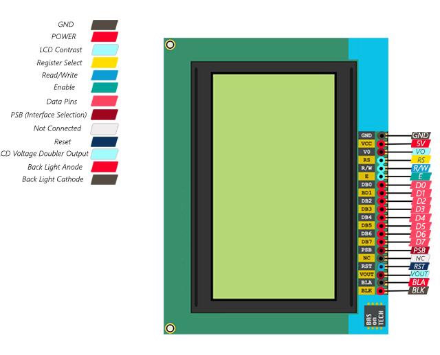
128×64 LCD Pinout
As I already mentioned, double-check with the manufacturer about the pinout of the Graphical LCD Module. The following table describes the pinout of the 128×64 LCD Module that I have.
| Pin Number | Pin Name | Pin Description |
| 1 | GND | Ground |
| 2 | VCC | Supply Voltage |
| 3 | VO | Contrast Adjust |
| 4 | RS | Register Select (CS in Serial) |
| 5 | RW | Read / Write Control (Serial Data In) |
| 6 | E | Enable (Serial CLK) |
| 7 – 14 | D0 – D7 | Data |
| 15 | PSB | Interface Selection (0: Serial, 1: 8-bit/4-bit Parallel) |
| 16 | NC | Not Connected |
| 17 | RST | Reset |
| 18 | VOUT | LCD Voltage Doubler Output |
| 19 | BLA | Backlight LED Anode |
| 20 | BLK | Backlight LED Cathode |
2. Interface with STM32:
The connection as following:
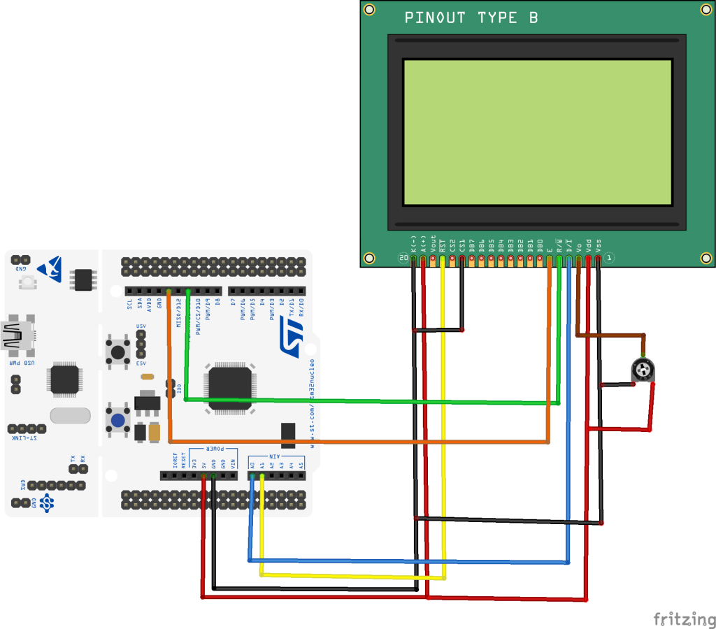
| STM32F411 Nucleo-64 | GLCD12864 |
| 5V | Vdd and LED+ (A) |
| GND | Vss, LED- (K) and PSB |
| PA0 | RS |
| PA1 | RST |
| PA7 (MOSI) | RW |
| PA5 (SCK) | En |
3. Developing the driver:
Before we develop the driver, take a look at the following:
- SPI and how to use it from here.
We start off by creating new spi.h header file.
Within the header file, include the header guard:
#ifndef SPI_H_
#define SPI_H_


#endif /* SPI_H_ */
Include stdint as following:
#include "stdint.h"
Declare the following functions:
void st7920_spi_pins_init();
void st7920_spi_config();
void st7920_spi_transmit(uint8_t *data,uint32_t size);
Hence, the header file as following:
#ifndef SPI_H_
#define SPI_H_

#include "stdint.h"

void st7920_spi_pins_init();
void st7920_spi_config();
void st7920_spi_transmit(uint8_t *data,uint32_t size);

#endif /* SPI_H_ */
Now, create spi.c source file.
Within the source file, include the following:
- Main spi header file.
- stm32f4 main header file
#include "spi.h"
#include "stm32f4xx.h"
Fot st7920_spi_pins_init function:
- Enable clock access to GPIOA.
- Set PA5, PA6 and PA5 to alternate function and set AF05 (SPI1) as alternate function.
- Set PA0 and PA1 as general output
void st7920_spi_pins_init()
{
	RCC->AHB1ENR|=RCC_AHB1ENR_GPIOAEN; //enable clock for GPIOA
	GPIOA->MODER|=GPIO_MODER_MODE0_0;
	GPIOA->MODER&=~GPIO_MODER_MODE0_1;

	GPIOA->MODER|=GPIO_MODER_MODE1_0;
	GPIOA->MODER&=~GPIO_MODER_MODE1_1;

	GPIOA->MODER|=GPIO_MODER_MODE4_0;
	GPIOA->MODER&=~GPIO_MODER_MODE4_1;

	GPIOA->MODER |=(GPIO_MODER_MODE5_1|GPIO_MODER_MODE6_1|GPIO_MODER_MODE7_1);
	GPIOA->MODER &=~(GPIO_MODER_MODE5_0|GPIO_MODER_MODE6_0|GPIO_MODER_MODE7_0);

	#define SPI1_AF 0x05

	GPIOA->AFR[0]|=(SPI1_AF<<GPIO_AFRL_AFSEL5_Pos)|(SPI1_AF<<GPIO_AFRL_AFSEL6_Pos)|(SPI1_AF<<GPIO_AFRL_AFSEL7_Pos);
}
For st7920_spi_config function:
- Enable clock access to SPI1.
- Set SPI to master mode.
- slave management to be software.
- SPI mode to mode1 (CPHA1 and CPOL0)
- Enable the module.
void st7920_spi_config()
{
	/*Enable clock access to SPI1 module*/
	RCC->APB2ENR |= RCC_APB2ENR_SPI1EN;

	/*Set MSB first*/
	SPI1->CR1 &=~ SPI_CR1_LSBFIRST;

	/*Set mode to MASTER*/
	SPI1->CR1 |= SPI_CR1_MSTR;

	/*Select software slave management by
	 * setting SSM=1 and SSI=1*/
	SPI1->CR1 |= SPI_CR1_SSM;
	SPI1->CR1 |= SPI_CR1_SSI;

	/*Set SPI mode to be MODE1 (CPHA1 CPOL0)*/
	SPI1->CR1|=SPI_CR1_CPHA;

	/*Enable SPI module*/
	SPI1->CR1 |= SPI_CR1_SPE;
}
For st7920_spi_transmit, it takes two parameters:
- Pointer to uint8_t array that holds the data to be written to GLCD.
- Size of the buffer.
void st7920_spi_transmit(uint8_t *data,uint32_t size)
{
	uint32_t i=0;

	while(i<size)
	{
		/*Wait until TXE is set*/
		while(!(SPI1->SR & (SPI_SR_TXE))){}

		/*Write the data to the data register*/
		SPI1->DR = data[i];
		i++;
	}
	/*Wait until TXE is set*/
	while(!(SPI1->SR & (SPI_SR_TXE))){}

	/*Wait for BUSY flag to reset*/
	while((SPI1->SR & (SPI_SR_BSY))){}

	/*Clear OVR flag*/
	(void)SPI1->DR;
	(void)SPI1->SR;
}
Hence, the source file as following:
#include "spi.h"
#include "stm32f4xx.h"


void st7920_spi_pins_init()
{
	RCC->AHB1ENR|=RCC_AHB1ENR_GPIOAEN; //enable clock for GPIOA
	GPIOA->MODER|=GPIO_MODER_MODE0_0;
	GPIOA->MODER&=~GPIO_MODER_MODE0_1;

	GPIOA->MODER|=GPIO_MODER_MODE1_0;
	GPIOA->MODER&=~GPIO_MODER_MODE1_1;

	GPIOA->MODER|=GPIO_MODER_MODE4_0;
	GPIOA->MODER&=~GPIO_MODER_MODE4_1;

	GPIOA->MODER |=(GPIO_MODER_MODE5_1|GPIO_MODER_MODE6_1|GPIO_MODER_MODE7_1);
	GPIOA->MODER &=~(GPIO_MODER_MODE5_0|GPIO_MODER_MODE6_0|GPIO_MODER_MODE7_0);

	#define SPI1_AF 0x05

	GPIOA->AFR[0]|=(SPI1_AF<<GPIO_AFRL_AFSEL5_Pos)|(SPI1_AF<<GPIO_AFRL_AFSEL6_Pos)|(SPI1_AF<<GPIO_AFRL_AFSEL7_Pos);
}

void st7920_spi_config()
{
	/*Enable clock access to SPI1 module*/
	RCC->APB2ENR |= RCC_APB2ENR_SPI1EN;

	/*Set MSB first*/
	SPI1->CR1 &=~ SPI_CR1_LSBFIRST;

	/*Set mode to MASTER*/
	SPI1->CR1 |= SPI_CR1_MSTR;

	/*Select software slave management by
	 * setting SSM=1 and SSI=1*/
	SPI1->CR1 |= SPI_CR1_SSM;
	SPI1->CR1 |= SPI_CR1_SSI;

	/*Set SPI mode to be MODE1 (CPHA1 CPOL0)*/
	SPI1->CR1|=SPI_CR1_CPHA;

	/*Enable SPI module*/
	SPI1->CR1 |= SPI_CR1_SPE;
}

void st7920_spi_transmit(uint8_t *data,uint32_t size)
{
	uint32_t i=0;

	while(i<size)
	{
		/*Wait until TXE is set*/
		while(!(SPI1->SR & (SPI_SR_TXE))){}

		/*Write the data to the data register*/
		SPI1->DR = data[i];
		i++;
	}
	/*Wait until TXE is set*/
	while(!(SPI1->SR & (SPI_SR_TXE))){}

	/*Wait for BUSY flag to reset*/
	while((SPI1->SR & (SPI_SR_BSY))){}

	/*Clear OVR flag*/
	(void)SPI1->DR;
	(void)SPI1->SR;
}
Thats all for the SPI section.
Now create new header file with name of ST7920.h .
With the header file, include the following:
#include "stdint.h"
Declare the following functions:
void ST7920_SendString(int row, int col, char* string);
void ST7920_GraphicMode (int enable) ;
void ST7920_DrawBitmap(const unsigned char* graphic);
void ST7920_Update(void);
void ST7920_Clear();
void ST7920_init();
void DrawLine(uint8_t x0, uint8_t y0, uint8_t x1, uint8_t y1);
void DrawRectangle(uint16_t x, uint16_t y, uint16_t w, uint16_t h);
void DrawFilledRectangle(uint16_t x, uint16_t y, uint16_t w, uint16_t h);
void DrawCircle(uint8_t x0, uint8_t y0, uint8_t radius);
void DrawFilledCircle(int16_t x0, int16_t y0, int16_t r);
void DrawTriangle(uint16_t x1, uint16_t y1, uint16_t x2, uint16_t y2, uint16_t x3, uint16_t y3);
void DrawFilledTriangle(uint16_t x1, uint16_t y1, uint16_t x2, uint16_t y2, uint16_t x3, uint16_t y3);
Hence the entire header file as following:
#ifndef ST7920_H_
#define ST7920_H_

#include "stdint.h"

void ST7920_SendString(int row, int col, char* string);
void ST7920_GraphicMode (int enable) ;
void ST7920_DrawBitmap(const unsigned char* graphic);
void ST7920_Update(void);
void ST7920_Clear();
void ST7920_init();
void DrawLine(uint8_t x0, uint8_t y0, uint8_t x1, uint8_t y1);
void DrawRectangle(uint16_t x, uint16_t y, uint16_t w, uint16_t h);
void DrawFilledRectangle(uint16_t x, uint16_t y, uint16_t w, uint16_t h);
void DrawCircle(uint8_t x0, uint8_t y0, uint8_t radius);
void DrawFilledCircle(int16_t x0, int16_t y0, int16_t r);
void DrawTriangle(uint16_t x1, uint16_t y1, uint16_t x2, uint16_t y2, uint16_t x3, uint16_t y3);
void DrawFilledTriangle(uint16_t x1, uint16_t y1, uint16_t x2, uint16_t y2, uint16_t x3, uint16_t y3);


#endif /* ST7920_H_ */
Now, create new source file with name of ST7920.c.
Within the source, include the following:
#include "ST7920.h"
#include "spi.h"
#include "delay.h"
Then define some macros for CS and RST pins as following:
#define CS_LOW 		GPIOA->BSRR=GPIO_BSRR_BR0
#define CS_HIGH		GPIOA->BSRR=GPIO_BSRR_BS0

#define RST_LOW 	GPIOA->BSRR=GPIO_BSRR_BR1
#define RST_HIGH	GPIOA->BSRR=GPIO_BSRR_BS1
Array to hold the data to be sent out to the display:
uint8_t lcd_data[3];
Variables to hold the display control:
uint8_t startRow, startCol, endRow, endCol; // coordinates of the dirty rectangle
uint8_t numRows = 64;
uint8_t numCols = 128;
uint8_t Graphic_Check = 0;
uint8_t image[(128 * 64)/8];
Some functions required for the operation:
#define LCD_CLS         0x01
#define LCD_HOME        0x02
#define LCD_ADDRINC     0x06
#define LCD_DISPLAYON   0x0C
#define LCD_DISPLAYOFF  0x08
#define LCD_CURSORON    0x0E
#define LCD_CURSORBLINK 0x0F
#define LCD_BASIC       0x30
#define LCD_EXTEND      0x34
#define LCD_GFXMODE     0x36
#define LCD_TXTMODE     0x34
#define LCD_STANDBY     0x01
#define LCD_SCROLL      0x03
#define LCD_SCROLLADDR  0x40
#define LCD_ADDR        0x80
#define LCD_LINE0       0x80
#define LCD_LINE1       0x90
#define LCD_LINE2       0x88
#define LCD_LINE3       0x98
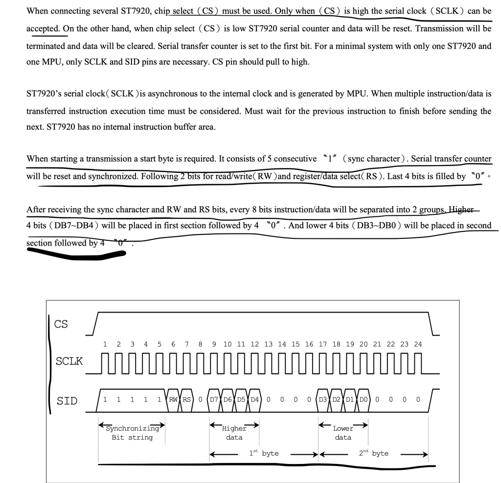
In order to send data/command, the datasheet clearly states the following:
- Set CS pin to high.
- Send 5bits of 1 to sync the display.
- Send RW and RS state.
- Followed by zero.
- Then send data/command as two byte as shown in figure below:
Hence, the send data command functions as following which have been defined as static:
static void ST7920_SendCmd (uint8_t cmd)
{
	CS_HIGH;  // PUll the CS high

	lcd_data[0]=0xF8;
	lcd_data[1]=(cmd&0xf0);
	lcd_data[2]=((cmd<<4)&0xf0);

	st7920_spi_transmit(lcd_data,3);

	delayuS(30);

	CS_LOW;  // PUll the CS LOW

}

static void ST7920_SendData (uint8_t data)
{

	CS_HIGH;

	lcd_data[0]=0xFA;
	lcd_data[1]=(data&0xf0);
	lcd_data[2]=((data<<4)&0xf0);

	st7920_spi_transmit(lcd_data,3);

	delayuS(30);

	CS_LOW;  // PUll the CS LOW
}
The delay will allow the GLCD to process the data since it doesn’t have internal buffer to store the data.
For the GLCD initializing sequence:
- Wait at least 40ms to ensure that GLCD is powered up
- Reset the GLCD by setting the reset pin low for 40 ms, then high.
- Send the initializing command.
void ST7920_init()
{
	delay(100);
	st7920_spi_pins_init();
	st7920_spi_config();

	RST_LOW;
	delay(50);
	RST_HIGH;
	delay(100);
	ST7920_SendCmd(0x30);  		// 8bit mode
	delayuS(110);  				//  >100us delay

	ST7920_SendCmd(0x30);  		// 8bit mode
	delayuS(40);  				// >37us delay

	ST7920_SendCmd(0x08);  // D=0, C=0, B=0
	delayuS(110);  // >100us delay

	ST7920_SendCmd(0x01);  // clear screen
	delay(12);  // >10 ms delay


	ST7920_SendCmd(0x06);  // cursor increment right no shift
	delay(1);  // 1ms delay

	ST7920_SendCmd(0x0C);  // D=1, C=0, B=0
	delay(1);  // 1ms delay

	ST7920_SendCmd(0x02);  // return to home
	delay(1);  // 1ms delay

}
Functions that allow us to display shapes, text pictures etc:
void ST7920_SendString(int row, int col, char* string)
{
    switch (row)
    {
        case 0:
            col |= 0x80;
            break;
        case 1:
            col |= 0x90;
            break;
        case 2:
            col |= 0x88;
            break;
        case 3:
            col |= 0x98;
            break;
        default:
            col |= 0x80;
            break;
    }

    ST7920_SendCmd(col);

    while (*string)
    	{
    		ST7920_SendData(*string++);
    	}
}


// switch to graphic mode or normal mode::: enable = 1 -> graphic mode enable = 0 -> normal mode

void ST7920_GraphicMode (int enable)   // 1-enable, 0-disable
{
	if (enable == 1)
	{
		ST7920_SendCmd(0x30);  // 8 bit mode
		delay (1);
		ST7920_SendCmd(0x34);  // switch to Extended instructions
		delay (1);
		ST7920_SendCmd(0x36);  // enable graphics
		delay (1);
		Graphic_Check = 1;  // update the variable
	}

	else if (enable == 0)
	{
		ST7920_SendCmd(0x30);  // 8 bit mode
		delay (1);
		Graphic_Check = 0;  // update the variable
	}
}

void ST7920_DrawBitmap(const unsigned char* graphic)
{
	uint8_t x, y;
	for(y = 0; y < 64; y++)
	{
		if(y < 32)
		{
			for(x = 0; x < 8; x++)							// Draws top half of the screen.
			{												// In extended instruction mode, vertical and horizontal coordinates must be specified before sending data in.
				ST7920_SendCmd(0x80 | y);				// Vertical coordinate of the screen is specified first. (0-31)
				ST7920_SendCmd(0x80 | x);				// Then horizontal coordinate of the screen is specified. (0-8)
				ST7920_SendData(graphic[2*x + 16*y]);		// Data to the upper byte is sent to the coordinate.
				ST7920_SendData(graphic[2*x+1 + 16*y]);	// Data to the lower byte is sent to the coordinate.
			}
		}
		else
		{
			for(x = 0; x < 8; x++)							// Draws bottom half of the screen.
			{												// Actions performed as same as the upper half screen.
				ST7920_SendCmd(0x80 | (y-32));			// Vertical coordinate must be scaled back to 0-31 as it is dealing with another half of the screen.
				ST7920_SendCmd(0x88 | x);
				ST7920_SendData(graphic[2*x + 16*y]);
				ST7920_SendData(graphic[2*x+1 + 16*y]);
			}
		}

	}
}


// Update the display with the selected graphics
void ST7920_Update(void)
{
	ST7920_DrawBitmap(image);
}


void ST7920_Clear()
{
	if (Graphic_Check == 1)  // if the graphic mode is set
	{
		uint8_t x, y;
		for(y = 0; y < 64; y++)
		{
			if(y < 32)
			{
				ST7920_SendCmd(0x80 | y);
				ST7920_SendCmd(0x80);
			}
			else
			{
				ST7920_SendCmd(0x80 | (y-32));
				ST7920_SendCmd(0x88);
			}
			for(x = 0; x < 8; x++)
			{
				ST7920_SendData(0);
				ST7920_SendData(0);
			}
		}
	}

	else
	{
		ST7920_SendCmd(0x01);   // clear the display using command
		delay(20); // delay >1.6 ms
	}
}


static void SetPixel(uint8_t x, uint8_t y)
{
  if (y < numRows && x < numCols)
  {
    uint8_t *p = image + ((y * (numCols/8)) + (x/8));
    *p |= 0x80u >> (x%8);

    *image = *p;

    // Change the dirty rectangle to account for a pixel being dirty (we assume it was changed)
    if (startRow > y) { startRow = y; }
    if (endRow <= y)  { endRow = y + 1; }
    if (startCol > x) { startCol = x; }
    if (endCol <= x)  { endCol = x + 1; }


  }

}

/* draw a line
 * start point (X0, Y0)
 * end point (X1, Y1)
 */
void DrawLine(uint8_t x0, uint8_t y0, uint8_t x1, uint8_t y1)
{
  int dx = (x1 >= x0) ? x1 - x0 : x0 - x1;
  int dy = (y1 >= y0) ? y1 - y0 : y0 - y1;
  int sx = (x0 < x1) ? 1 : -1;
  int sy = (y0 < y1) ? 1 : -1;
  int err = dx - dy;

  for (;;)
  {
    SetPixel(x0, y0);
    if (x0 == x1 && y0 == y1) break;
    int e2 = err + err;
    if (e2 > -dy)
    {
      err -= dy;
      x0 += sx;
    }
    if (e2 < dx)
    {
      err += dx;
      y0 += sy;
    }
  }
}


/* Draw rectangle
 * start point (x,y)
 * w -> width
 * h -> height
 */
void DrawRectangle(uint16_t x, uint16_t y, uint16_t w, uint16_t h)
{
	/* Check input parameters */
	if (
		x >= numCols ||
		y >= numRows
	) {
		/* Return error */
		return;
	}

	/* Check width and height */
	if ((x + w) >= numCols) {
		w = numCols - x;
	}
	if ((y + h) >= numRows) {
		h = numRows - y;
	}

	/* Draw 4 lines */
	DrawLine(x, y, x + w, y);         /* Top line */
	DrawLine(x, y + h, x + w, y + h); /* Bottom line */
	DrawLine(x, y, x, y + h);         /* Left line */
	DrawLine(x + w, y, x + w, y + h); /* Right line */
}


/* Draw filled rectangle
 * Start point (x,y)
 * w -> width
 * h -> height
 */
void DrawFilledRectangle(uint16_t x, uint16_t y, uint16_t w, uint16_t h)
{
	uint8_t i;

	/* Check input parameters */
	if (
		x >= numCols ||
		y >= numRows
	) {
		/* Return error */
		return;
	}

	/* Check width and height */
	if ((x + w) >= numCols) {
		w = numCols - x;
	}
	if ((y + h) >= numRows) {
		h = numRows - y;
	}

	/* Draw lines */
	for (i = 0; i <= h; i++) {
		/* Draw lines */
		DrawLine(x, y + i, x + w, y + i);
	}
}


/* draw circle
 * centre (x0,y0)
 * radius = radius
 */
void DrawCircle(uint8_t x0, uint8_t y0, uint8_t radius)
{
  int f = 1 - (int)radius;
  int ddF_x = 1;

  int ddF_y = -2 * (int)radius;
  int x = 0;

  SetPixel(x0, y0 + radius);
  SetPixel(x0, y0 - radius);
  SetPixel(x0 + radius, y0);
  SetPixel(x0 - radius, y0);

  int y = radius;
  while(x < y)
  {
    if(f >= 0)
    {
      y--;
      ddF_y += 2;
      f += ddF_y;
    }
    x++;
    ddF_x += 2;
    f += ddF_x;
    SetPixel(x0 + x, y0 + y);
    SetPixel(x0 - x, y0 + y);
    SetPixel(x0 + x, y0 - y);
    SetPixel(x0 - x, y0 - y);
    SetPixel(x0 + y, y0 + x);
    SetPixel(x0 - y, y0 + x);
    SetPixel(x0 + y, y0 - x);
    SetPixel(x0 - y, y0 - x);
  }
}


// Draw Filled Circle

void DrawFilledCircle(int16_t x0, int16_t y0, int16_t r)
{
	int16_t f = 1 - r;
	int16_t ddF_x = 1;
	int16_t ddF_y = -2 * r;
	int16_t x = 0;
	int16_t y = r;

    SetPixel(x0, y0 + r);
    SetPixel(x0, y0 - r);
    SetPixel(x0 + r, y0);
    SetPixel(x0 - r, y0);
    DrawLine(x0 - r, y0, x0 + r, y0);

    while (x < y) {
        if (f >= 0) {
            y--;
            ddF_y += 2;
            f += ddF_y;
        }
        x++;
        ddF_x += 2;
        f += ddF_x;

        DrawLine(x0 - x, y0 + y, x0 + x, y0 + y);
        DrawLine(x0 + x, y0 - y, x0 - x, y0 - y);

        DrawLine(x0 + y, y0 + x, x0 - y, y0 + x);
        DrawLine(x0 + y, y0 - x, x0 - y, y0 - x);
    }
}


// Draw Traingle with coordimates (x1, y1), (x2, y2), (x3, y3)
void DrawTriangle(uint16_t x1, uint16_t y1, uint16_t x2, uint16_t y2, uint16_t x3, uint16_t y3)
{
	/* Draw lines */
	DrawLine(x1, y1, x2, y2);
	DrawLine(x2, y2, x3, y3);
	DrawLine(x3, y3, x1, y1);
}


// Draw Filled Traingle with coordimates (x1, y1), (x2, y2), (x3, y3)
void DrawFilledTriangle(uint16_t x1, uint16_t y1, uint16_t x2, uint16_t y2, uint16_t x3, uint16_t y3)
{
	int16_t deltax = 0, deltay = 0, x = 0, y = 0, xinc1 = 0, xinc2 = 0,
	yinc1 = 0, yinc2 = 0, den = 0, num = 0, numadd = 0, numpixels = 0,
	curpixel = 0;

#define ABS(x)   ((x) > 0 ? (x) : -(x))

	deltax = ABS(x2 - x1);
	deltay = ABS(y2 - y1);
	x = x1;
	y = y1;

	if (x2 >= x1) {
		xinc1 = 1;
		xinc2 = 1;
	} else {
		xinc1 = -1;
		xinc2 = -1;
	}

	if (y2 >= y1) {
		yinc1 = 1;
		yinc2 = 1;
	} else {
		yinc1 = -1;
		yinc2 = -1;
	}

	if (deltax >= deltay){
		xinc1 = 0;
		yinc2 = 0;
		den = deltax;
		num = deltax / 2;
		numadd = deltay;
		numpixels = deltax;
	} else {
		xinc2 = 0;
		yinc1 = 0;
		den = deltay;
		num = deltay / 2;
		numadd = deltax;
		numpixels = deltay;
	}

	for (curpixel = 0; curpixel <= numpixels; curpixel++)
	{
		DrawLine(x, y, x3, y3);

		num += numadd;
		if (num >= den) {
			num -= den;
			x += xinc1;
			y += yinc1;
		}
		x += xinc2;
		y += yinc2;
	}
}
In main.c:
#include "delay.h"
#include "bitmap.h"
#include "stdio.h"
#include "horse.h"
#include "ST7920.h"


int main(void)
{

	ST7920_init();

	ST7920_SendString(0,0, "HELLO WORLD");
	ST7920_SendString(1,0, "FROM");
	ST7920_SendString(2,0, "EmbeddedExpertIO");
	ST7920_SendString(3,0, "1234567890!@#$%^");
	delay(2000);
	ST7920_Clear();
	ST7920_GraphicMode(1);
	ST7920_DrawBitmap(logo);
	delay(2000);
	ST7920_Clear();
	DrawCircle(110, 31, 12);

	DrawCircle(110, 31, 16);

	DrawLine(3, 60, 127, 33);

	ST7920_Update();

	delay(2000);

	DrawRectangle (100, 12, 20, 14);

	ST7920_Update();

	delay(2000);

	DrawFilledRectangle(30, 20, 30, 10);

	ST7920_Update();

	delay(2000);

	DrawFilledCircle(15, 30, 6);

	ST7920_Update();

	DrawFilledTriangle(1,5,10,5,6,15);

	ST7920_Update();

	delay(2000);

	ST7920_Clear();


	while(1)
	{
		ST7920_DrawBitmap(horse1);
		ST7920_DrawBitmap(horse2);
		ST7920_DrawBitmap(horse3);
		ST7920_DrawBitmap(horse4);
		ST7920_DrawBitmap(horse5);
		ST7920_DrawBitmap(horse6);
		ST7920_DrawBitmap(horse7);
		ST7920_DrawBitmap(horse8);
		ST7920_DrawBitmap(horse9);
		ST7920_DrawBitmap(horse10);
	}

}
4. Code:
You may download the entire code from here:
5. Results:
Happy coding 🙂
15 Comments
Good evening, I would like to contact you to find out if there is a solution to correct the pixel bug at the top left of the screen, thank you in advance for your response. Paul
Hi,
post your bug here and we will look at it.
In your YouTube video, you can see that there are extra pixels at the top left of the screen when you draw a shape.
I have the solution, you just have to delete the line “*image = *p;” in the “SetPixel()” function
I have the solution to fix the pixel bug at the top left of the screen, just remove “*image = *p;” in ST7920.c
I have another question how I could display a custom font and font size with free coordinates?
Hi,
you could use graphic mode to display string in the desired size.
Ok thanks you!
Hello paul, did you manage to display a custom font and font size?
Hi Paul, did you managed to display a custom Font and its size?
Hello, I would like to bother you again because I cannot get the program to work to display on a st7920 with an stm32f767zi even though I have adapted each command for the microcontroller, is it possible to help me, thank you in advance
I have found the problem
https://github.com/TESSON-MAKER/ST7920-for-STM32F7
Hi,
what was the issue?
The issue stemmed from the SPI speed, the corrected output voltage of PA7 (2.6V) achieved by removing a jumper on the card, and the required data format for transmission.
Hello, how to display a custom font and font size use this library?
Thank you
Add Comment