
In the previous guide (here), we took a look how to configure a pin to work in alternate function. In this guide, we shall take this further by connecting the configured GPIO in alternate function to UART.
In this guide, we shall cover the following:
- Creating UART Board Support Package header file.
- Creating UART Board Support Package source file.
- Code.
- Results.
1. Creating UART Board Support Package header file:
Before going into the creating the header file, refer to this topic about uart here.
We start off by creating new header file with name of uart_bsp.h
After creating the header file, include the following header files:
#include "stdint.h"

#include "stm32f4xx.h"
We shall create enum to hold the status of UART for the following:
- UART_SUCCESS.
- UART_FAILED.
- UART_TIMEOUT.
typedef enum
{
	UART_SUCCESS=0,
	UART_FAILED =-1,
	UART_TIMEOUT=-2
}UART_StatusTypedef;
We shall also declare enum to hold the mode of UART:
- TX only.
- RX only.
- TX and RX.
typedef enum
{

	UART_TX_Only=0,
	UART_RX_Only=1,
	UART_TX_RX=2

}UART_DirectionTypedef;
Create new struct to hold the configuration parameters for the following:
- Bus Speed.
- Buad Rate.
- Mode.
typedef struct
{
	uint32_t busSpeed;
	uint32_t buadRate;
	uint8_t mode;

}UART_ConfigTypedef;
Declare the following three functions:
void UART2_CLOCK_ENABLE(void);

void BSP_UART_Init(USART_TypeDef *uart, UART_ConfigTypedef *config);

UART_StatusTypedef BSP_UART_Write_Char(USART_TypeDef *uart,char ch, uint32_t timeout);
First one to enable clock access to UART2.
The second one to configure the UART.
Third one to write a single character to UART.
Hence, the entire header file as following:
#ifndef UART_BSP_H_
#define UART_BSP_H_

#include "stdint.h"

#include "stm32f4xx.h"


typedef enum
{
	UART_SUCCESS=0,
	UART_FAILED =-1,
	UART_TIMEOUT=-2
}UART_StatusTypedef;

/**
 * @brief This enum represents the direction of UART
 */

typedef enum
{

	UART_TX_Only=0,
	UART_RX_Only=1,
	UART_TX_RX=2

}UART_DirectionTypedef;


typedef struct
{
	uint32_t busSpeed;
	uint32_t buadRate;
	uint8_t mode;

}UART_ConfigTypedef;

void UART2_CLOCK_ENABLE(void);

void BSP_UART_Init(USART_TypeDef *uart, UART_ConfigTypedef *config);

UART_StatusTypedef BSP_UART_Write_Char(USART_TypeDef *uart,char ch, uint32_t timeout);

#endif /* UART_BSP_H_ */
2. Creating UART Board Support Package source code:
Create new source file with name of uart_bsp.c
Within the source file, include the following:
#include "uart_bsp.h"
#include "bsp.h"
Declare the following prototypes of static functions:
static void uart_set_baudrate(USART_TypeDef *USARTx, uint32_t PeriphClk,  uint32_t BaudRate);
static uint16_t compute_uart_bd(uint32_t PeriphClk, uint32_t BaudRate);
Those function will set the baudrate.
For enabling clock access to UART2 function:
void UART2_CLOCK_ENABLE(void)
{
	RCC->APB1ENR|=RCC_APB1ENR_USART2EN;
}
For board support package uart intiailization function:
void BSP_UART_Init(USART_TypeDef *uart, UART_ConfigTypedef *config)
{
	switch (config->mode)
	{
		case UART_TX_Only: 	uart->CR1=USART_CR1_TE; break;

		case UART_RX_Only:  uart->CR1=USART_CR1_RE; break;

		case UART_TX_RX:	uart->CR1=USART_CR1_RE|USART_CR1_TE; break;

		default : break;
	}

	uart_set_baudrate(uart, config->busSpeed, config->buadRate);

	uart->CR1|= USART_CR1_UE;

}
For writing a single character function:
UART_StatusTypedef BSP_UART_Write_Char(USART_TypeDef *uart,char ch, uint32_t timeout)
{
	uint32_t start_ticks= BSP_Get_Ticks();

	/*Make sure the transmit data register is empty*/
	while(!(uart->SR & USART_SR_TXE))
	{
		if(BSP_Get_Ticks()-start_ticks>timeout)
		{
			return UART_TIMEOUT;
		}
	}

	/*Write to transmit data register*/
	uart->DR	=  (ch & 0xFF);

	return UART_SUCCESS;
}
For setting the baud rate functions:
static void uart_set_baudrate(USART_TypeDef *USARTx, uint32_t PeriphClk,  uint32_t BaudRate)
{
	USARTx->BRR =  compute_uart_bd(PeriphClk,BaudRate);
}

static uint16_t compute_uart_bd(uint32_t PeriphClk, uint32_t BaudRate)
{
	return ((PeriphClk + (BaudRate/2U))/BaudRate);
}
Note: all those steps have been mentioned here.
Hence, the entire source code as following:
#include "uart_bsp.h"
#include "bsp.h"


static void uart_set_baudrate(USART_TypeDef *USARTx, uint32_t PeriphClk,  uint32_t BaudRate);
static uint16_t compute_uart_bd(uint32_t PeriphClk, uint32_t BaudRate);


void UART2_CLOCK_ENABLE(void)
{
	RCC->APB1ENR|=RCC_APB1ENR_USART2EN;
}

void BSP_UART_Init(USART_TypeDef *uart, UART_ConfigTypedef *config)
{
	switch (config->mode)
	{
		case UART_TX_Only: 	uart->CR1=USART_CR1_TE; break;

		case UART_RX_Only:  uart->CR1=USART_CR1_RE; break;

		case UART_TX_RX:	uart->CR1=USART_CR1_RE|USART_CR1_TE; break;

		default : break;
	}

	uart_set_baudrate(uart, config->busSpeed, config->buadRate);

	uart->CR1|= USART_CR1_UE;

}


UART_StatusTypedef BSP_UART_Write_Char(USART_TypeDef *uart,char ch, uint32_t timeout)
{
	uint32_t start_ticks= BSP_Get_Ticks();

	/*Make sure the transmit data register is empty*/
	while(!(uart->SR & USART_SR_TXE))
	{
		if(BSP_Get_Ticks()-start_ticks>timeout)
		{
			return UART_TIMEOUT;
		}
	}

	/*Write to transmit data register*/
	uart->DR	=  (ch & 0xFF);

	return UART_SUCCESS;
}


static void uart_set_baudrate(USART_TypeDef *USARTx, uint32_t PeriphClk,  uint32_t BaudRate)
{
	USARTx->BRR =  compute_uart_bd(PeriphClk,BaudRate);
}

static uint16_t compute_uart_bd(uint32_t PeriphClk, uint32_t BaudRate)
{
	return ((PeriphClk + (BaudRate/2U))/BaudRate);
}
3. Code:
You may download the entire source code from here:
4. Results:
In main.c:
#include "bsp.h"
#include "uart_bsp.h"
void clock_config(void);


int main()
{

	clock_config();

	GPIOA_CLOCK_ENABLE();

	GPIO_Configure_Typedef PA2_ALT;

	PA2_ALT.PinNumber=pin2;
	PA2_ALT.Mode=Alternate_function;
	PA2_ALT.AlternateType=AF7;
	GPIO_Initialization(GPIOA,&PA2_ALT);

	UART2_CLOCK_ENABLE();

	UART_ConfigTypedef uart_config;

	uart_config.buadRate=115200;
	uart_config.busSpeed=50000000;
	uart_config.mode=UART_TX_Only;

	BSP_UART_Init(USART2, &uart_config);

	BSP_Ticks_Init(100000000);


	while(1)
	{

		BSP_UART_Write_Char(USART2,'A',10);
		BSP_UART_Write_Char(USART2,'\r',10);
		BSP_UART_Write_Char(USART2,'\n',10);
		BSP_Delay(1000);
	}

}

void clock_config(void)
{
	Clock_Config_Typedef clockConfig;

	clockConfig.PLL_M= 4;
	clockConfig.PLL_N= 200;
	clockConfig.PLL_P= 4;

	clockConfig.AHB1Prescaler=AHB1_Prescaler1;
	clockConfig.APB1Prescaler=APB1_Prescaler2;
	clockConfig.APB2Prescaler=APB2_Prescaler1;

	clockConfig.clockSourc=External_Oscillator;
	clockConfig.flash_latency= Three_wait_state;

	Clock_Configuration(&clockConfig);
}
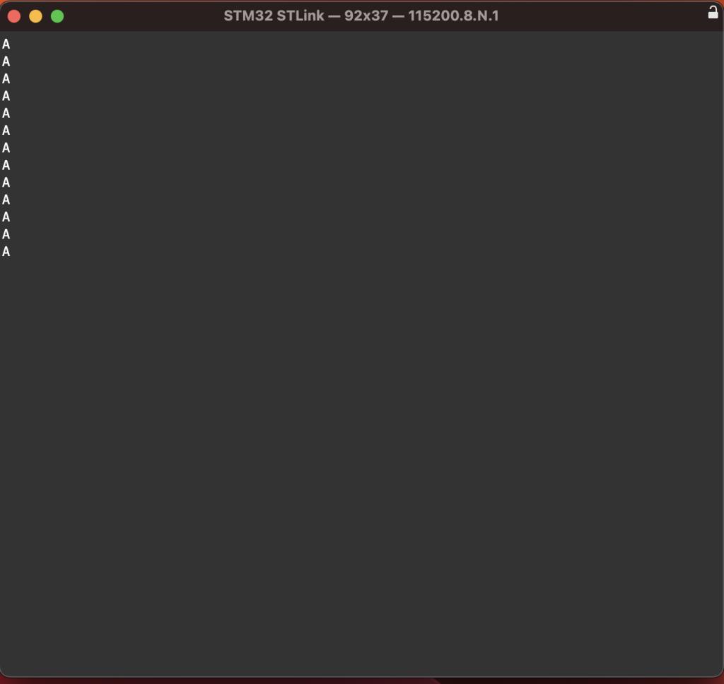
You should get the following results:
Happy coding 🙂
Add Comment