In the previous part (here), we saw how to configure the ADC to work in DMA mode with timer trigger. In this guide, we shall use feature called analog watchdog. This has benefits like monitoring level of water etc.
In this guide, we shall cover the following:
- What is analog watchdog.
- Connection
- Developing the code.
- Code.
- Results.
1. What is Analog Watchdog:
Analog watchdog is a mechanism that allow the ADC to generate interrupt when the ADC values is above the high threshold level and below low threshold level.

This can be used to detect a pulse from impact sensor, irregularity within the power bus etc. The only limitation is your imagination.
2. Connection:
The connection as following:
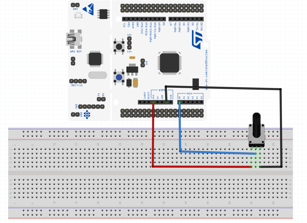
The middle pin of the potentiometer is connected to the PA0 (Arduino A0 in case of F411).
3. Developing the Code:
First, create a source and header file named adc_watchdog.c and adc_watchdog.h respectively. Within the header file, the following is declared.
#ifndef ADC_WATCHDOG_H_
#define ADC_WATCHDOG_H_
#include "stdint.h"

void adc_watchDog_Init(uint16_t low_threshold, uint16_t high_threshold);


#endif /* ADC_WATCHDOG_H_ */
Within the source file, start by including the adc_watchdog.h and STM32F4xx header file:
#include "adc_watchdog.h"
#include "stm32f4xx.h"
Declare the following function which takes two arguments:
- Low threshold.
- High threshold.
void adc_watchDog_Init(uint16_t low_threshold, uint16_t high_threshold)
Within the function, set PA0 to analog mode:
	/*Enable clock access to GPIOA*/
	RCC->AHB1ENR|=RCC_AHB1ENR_GPIOAEN;
	/*Set PA0 as analog mode*/
	GPIOA->MODER|=GPIO_MODER_MODE0;
Then enable clock access to ADC1:
	/*Enable clock access to ADC1*/
	RCC->APB2ENR|=RCC_APB2ENR_ADC1EN;
Enable continuous conversion:
	/*Enable continuous conversion*/
	ADC1->CR2|=ADC_CR2_CONT;
From the Control Register 1 (CR1), set the analog watchdog to monitor single channel as following:
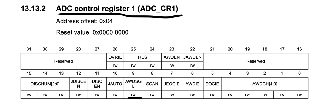
	/*Enable watch dog on single channel*/
	ADC1->CR1|=ADC_CR1_AWDSGL;
Then enable AWD interrupt within CR1:
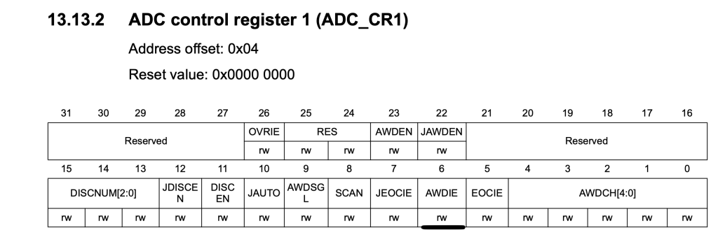
	/*Enable watch dog interrupt*/

	ADC1->CR1|=ADC_CR1_AWDIE;
Enable ADC interrupt within NVIC:
	/*Enable ADC1 interrupt in NVIC*/
	NVIC_EnableIRQ(ADC_IRQn);
Also, set the low threshold value as following:
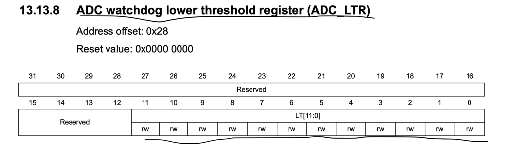
	/*Set the low threshold*/

	ADC1->LTR=0;
	ADC1->LTR=low_threshold;
Then set the high threshold:
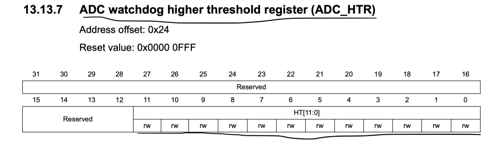
	/*Set the high threshold*/

	ADC1->HTR=0;
	ADC1->HTR=high_threshold;
Set the channel to be monitored as channel0:
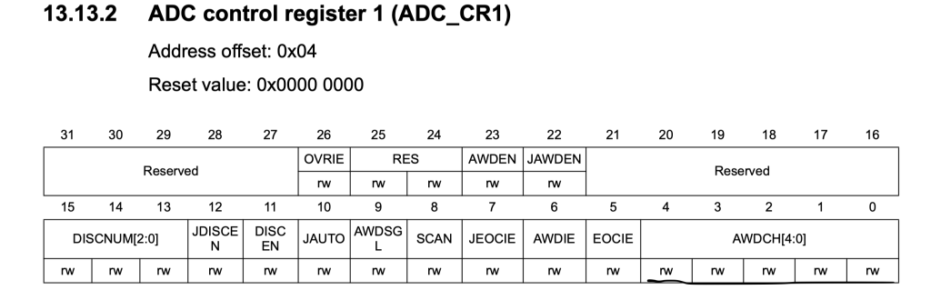
	/*Set watch dog channel channel to be channel 0*/

	ADC1->CR1&=~(0x1F<<ADC_CR1_AWDCH_Pos);
Enable the watch dog:
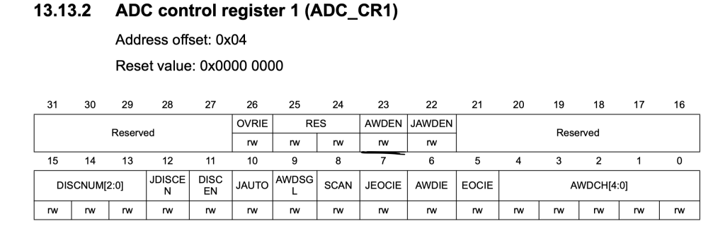
	/*Enable analog watchdog on regular channel*/

	ADC1->CR1|=ADC_CR1_AWDEN;
Finally start the ADC:
	/*Enable the ADC module*/

	ADC1->CR2|=ADC_CR2_ADON;

	/*Start the conversion*/

	ADC1->CR2|=ADC_CR2_SWSTART;
Thats all for the source code.
Within the main.c, we shall handle the interrupt from watchdog:
Within the interrupt handler, check if the source is AWD by checking AWD bit in SR register:
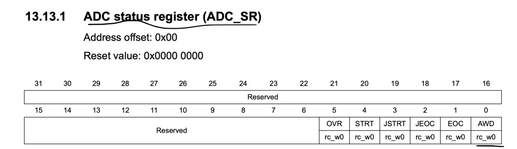
If the source is AWD, set watchDogTrig variable to 1 then clear the status register.
void ADC_IRQHandler(void)
{
	if(ADC1->SR & ADC_SR_AWD)
	{
		watchDogTrig=1;
		ADC1->SR &=~ADC_SR_AWD;

	}
}
With main function, initialize the wathcdog as following:
adc_watchDog_Init(100,2500);
within while(1) loop:
while(!(ADC1->SR & ADC_SR_EOC));
		adc_data=ADC1->DR;
		printf("ADC value is %d\r\n",adc_data);
		if(watchDogTrig==1)
		{
			watchDogTrig=0;
			printf("WatchDog Triggered\r\n");
			if(adc_data<=100)printf("Pump is ON\r\n");
			if(adc_data>=2500)printf("Pump is OFF\r\n");
		}

		delay(300);

	}
4. Code:
You may download the source code from here:
5. Results:
Happy coding 🙂
Add Comment