

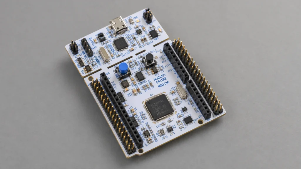
In this eighth part of Board Support Package, we shall develop interrupt driver for UART2 to receive a single character and toggle an LED to indicate that STM32 received the character.
In this guide, we shall cover the following:
- Developing the header file.
- Developing the source code.
- Main code.
- Results.
1. Developing the header file:
From the previous guide about UART in TX and RX here.
For more information about how character reception in interrupt mode, please refer to this guide here.
Open uart_bsp.h.
Declare the following enum which define the interrupt source and if the main interrupt is enabled or not:
typedef enum
{
	Interrupt_disabled=0, /*No interrupt*/
	Interrupt_Enabled=1, /*Interrupt enabled*/

	TXEIE_Enable=1, /*Transmit buffer is empty*/
	RXNEIE_Enable=1, /*Receiver buffer is not empty*/
	IDLEIE_Enable=1, /*IDLE Line detection enabled*/

}Interrupt_Source_Typedef;
Since STM32F411 has three UART as following:
- USART1.
- USART2.
- UART6.
We shall declare enum to handle which uart to be used as following:
typedef enum
{
	usart1=0,
	usart2=1,
	uart6=2,
}USART_NumberTypedef;
This for enabling the interrupt in NVIC.
Within UART_ConfigTypedef datastruct, include the following:
	uint8_t InterrupteEnbable;
	uint8_t TX_InterruptEnable;
	uint8_t RX_InterruptEnable;
	uint8_t IDLE_Line_Interrupt_Enable;
	uint8_t uart_number;
Hence, the updated data structure as following:
typedef struct
{
	uint32_t busSpeed;
	uint32_t buadRate;
	uint8_t mode;
	uint8_t InterrupteEnbable;
	uint8_t TX_InterruptEnable;
	uint8_t RX_InterruptEnable;
	uint8_t IDLE_Line_Interrupt_Enable;
	uint8_t uart_number;
}UART_ConfigTypedef;
Thats all for the header file.
2. Developing the source code:
Open uart_bsp.c source file.
Within this function:
void BSP_UART_Init(USART_TypeDef *uart, UART_ConfigTypedef *config)
Before enabling the UART:
Check if the interrupt is enabled or not:
if (config->InterrupteEnbable==Interrupt_Enabled)
If it is enabled, enable the required one in NVIC:
switch (config->uart_number)
		{
			case usart2: NVIC_EnableIRQ(USART2_IRQn); break;
			case usart1: NVIC_EnableIRQ(USART1_IRQn); break;
			case uart6: NVIC_EnableIRQ(USART6_IRQn); break;
			default: break;

		}
Check which interrupts are needed:
		if (config->TX_InterruptEnable==TXEIE_Enable)
		{
			uart->CR1|= USART_CR1_TXEIE;
		}

		if(config->RX_InterruptEnable==RXNEIE_Enable)
		{
			uart->CR1|= USART_CR1_RXNEIE;
		}

		if(config->IDLE_Line_Interrupt_Enable==IDLEIE_Enable)
		{
			uart->CR1|=USART_CR1_IDLEIE;
		}
Hence, the updated version of BSP_UART_Init as following:
void BSP_UART_Init(USART_TypeDef *uart, UART_ConfigTypedef *config)
{
	switch (config->mode)
	{
		case UART_TX_Only: 	uart->CR1=USART_CR1_TE; break;

		case UART_RX_Only:  uart->CR1=USART_CR1_RE; break;

		case UART_TX_RX:	uart->CR1=USART_CR1_RE|USART_CR1_TE; break;

		default : break;
	}

	uart_set_baudrate(uart, config->busSpeed, config->buadRate);


	if (config->InterrupteEnbable==Interrupt_Enabled)
	{
		switch (config->uart_number)
		{
			case usart2: NVIC_EnableIRQ(USART2_IRQn); break;
			case usart1: NVIC_EnableIRQ(USART1_IRQn); break;
			case uart6: NVIC_EnableIRQ(USART6_IRQn); break;
			default: break;

		}

		if (config->TX_InterruptEnable==TXEIE_Enable)
		{
			uart->CR1|= USART_CR1_TXEIE;
		}

		if(config->RX_InterruptEnable==RXNEIE_Enable)
		{
			uart->CR1|= USART_CR1_RXNEIE;
		}

		if(config->IDLE_Line_Interrupt_Enable==IDLEIE_Enable)
		{
			uart->CR1|=USART_CR1_IDLEIE;
		}
	}


	uart->CR1|= USART_CR1_UE;

}
For the interrupt handler:
void USART1_IRQHandler(void)
{
	uart1_interrupt_handler();
	NVIC_ClearPendingIRQ(USART1_IRQn);
}


void USART2_IRQHandler(void)
{
	uart2_interrupt_handler();
	NVIC_ClearPendingIRQ(USART2_IRQn);
}

void USART6_IRQHandler(void)
{
	uart6_interrupt_handler();
	NVIC_ClearPendingIRQ(USART6_IRQn);
}
For interrupt handler to be implemented by the user:
__WEAK void uart1_interrupt_handler(void){}
__WEAK void uart2_interrupt_handler(void){}
__WEAK void uart6_interrupt_handler(void){}
Thats all for the source code.
Related course
Connect this BSP component to the driver fundamentals
The receive interrupt now reaches an application-defined callback. Explore the STM32F4 bare-metal course for a structured treatment of the underlying peripheral and related drivers. Use the lessons to understand the hardware decisions behind this BSP, with its specific API supplied by the article.
3. Main code:
In main.c:
#include "bsp.h"
#include "uart_bsp.h"
#include "exti_bsp.h"

GPIO_Output_Typedef LED;


void clock_config(void);


int main()
{

	clock_config();

	GPIOA_CLOCK_ENABLE();
	GPIOC_CLOCK_ENABLE();

	GPIO_Configure_Typedef LED_Config;
	LED_Config.PinNumber=pin5;
	LED_Config.Mode=OUTPUT;
	LED.pinNumber=pin5;
	GPIO_Initialization(GPIOA,&LED_Config);

	GPIO_Configure_Typedef PA3_Config;
	PA3_Config.PinNumber=pin3;
	PA3_Config.Mode=Alternate_function;
	PA3_Config.AlternateType=AF7;
	GPIO_Initialization(GPIOA,&PA3_Config);

	UART2_CLOCK_ENABLE();

	UART_ConfigTypedef uart;

	uart.buadRate=115200;
	uart.busSpeed=50000000;
	uart.mode=UART_RX_Only;
	uart.InterrupteEnbable=Interrupt_Enabled;
	uart.RX_InterruptEnable=RXNEIE_Enable;
	uart.uart_number=usart2;
	BSP_UART_Init(USART2,&uart);


	BSP_Ticks_Init(100000000);


	while(1)
	{


	}

}

void clock_config(void)
{
	Clock_Config_Typedef clockConfig;

	clockConfig.PLL_M= 4;
	clockConfig.PLL_N= 200;
	clockConfig.PLL_P= 4;

	clockConfig.AHB1Prescaler=AHB1_Prescaler1;
	clockConfig.APB1Prescaler=APB1_Prescaler2;
	clockConfig.APB2Prescaler=APB2_Prescaler1;

	clockConfig.clockSourc=External_Oscillator;
	clockConfig.flash_latency= Three_wait_state;

	Clock_Configuration(&clockConfig);
}

void uart2_interrupt_handler(void)
{
	if (USART2->SR & USART_SR_RXNE) /*Check if the interrupt source is RXNE*/
	{
		(void)USART2->DR;			/*Read the DR register to clear everything*/

		GPIO_TogglePin(GPIOA,&LED); /*Toggle the LED to for character reception*/

	}

}
Since we are interested only in RX part, no need to declare the UART as full duplex.
4. Results:
Open any terminal program and set the buadrate to be 115200 and send any character and the built-in LED should toggle each time you send a character.

Board Support Package for STM32F411: UART Reception in interrupt mode
Hosted by YouTube. Playing may use YouTube cookies. Privacy details
Happy coding 🙂
Discussion