
In this guide, we shall interface STM32 with GLCD12864 using serial method. We shall display some texts, shapes and graphics.
In the guide, we will cover the following:
- GLCD 12864.
- Interface with STM32.
- Code.
- Demo.
1. GLCD 12864:
Ordinary LCDs can only display simple text or numbers within a fixed size. But in 128×64 graphical LCD display, there is 128×64 = 8192 dots, which is equivalent to 8242/8 = 1024 pixels. So, it can display not only simple text or numbers within a fixed size but also simple graphics.
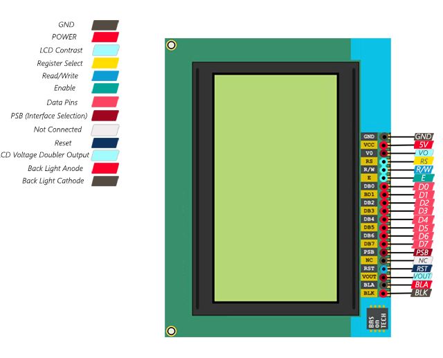
128×64 Graphical LCD Display Pinout
This module has 20 pins:
- GND: Ground
- VCC: Module power supply – 5 V
- VO: LCD Contrast
- RS: Register Select Pin
- R/W: Write/ Read selection
- E: Enable Signal
- D0-7: Data Bus
- PSB: Interface selection (0 for serial communication, 1 for 8-bit parallel communication)
- NC: Not Connected
- RST: Reset
- Vout: LCD Voltage Output (Vout < 7V)
- BLA: Power Supply for Backlight+
- BLK: Power Supply for Backlight-
You can see the pinout of this module in the image below.
2. Interface with STM32:
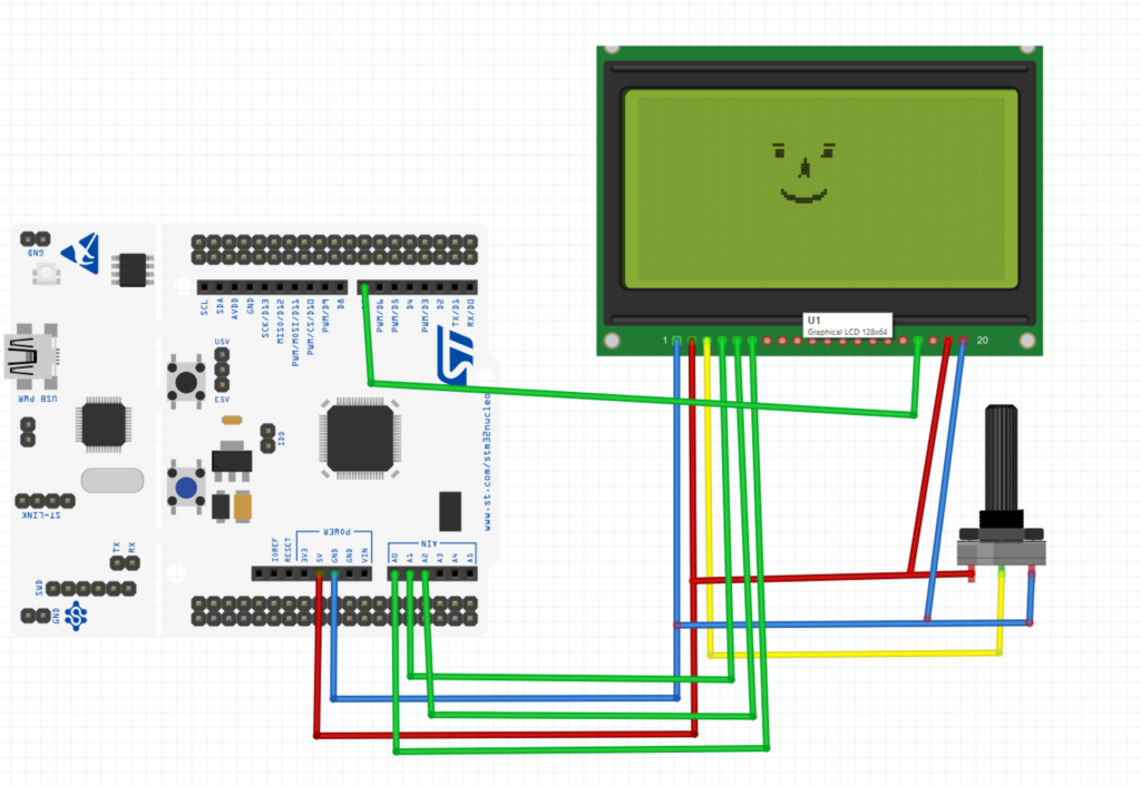
setup below is as follows
PA0 ———> SCLK (EN)
PA1 ———> CS (RS)
PA4 ———> SID (RW)
PA8 ———> RST (RST)
3. Code:
We start of by defining some marcos fpr SCLK, CS, SID and RST as following:
#define SCK_LOW 	(GPIOA->BSRR=GPIO_BSRR_BR0)
#define SCK_HIGH 	(GPIOA->BSRR=GPIO_BSRR_BS0)

#define CS_LOW 		(GPIOA->BSRR=GPIO_BSRR_BR1)
#define CS_HIGH 	(GPIOA->BSRR=GPIO_BSRR_BS1)

#define SID_LOW 	(GPIOA->BSRR=GPIO_BSRR_BR4)
#define SID_HIGH 	(GPIOA->BSRR=GPIO_BSRR_BS4)

#define RST_LOW 	(GPIOA->BSRR=GPIO_BSRR_BR8)
#define RST_HIGH 	(GPIOA->BSRR=GPIO_BSRR_BS8)
Now we can need some variables as following:
uint8_t startRow, startCol, endRow, endCol; // coordinates of the dirty rectangle
uint8_t numRows = 64;
uint8_t numCols = 128;
uint8_t Graphic_Check = 0;
uint8_t image[(128 * 64)/8];
For initializing the lcd:
void ST7920_Init (void)
{

	RCC->AHB1ENR|=RCC_AHB1ENR_GPIOAEN;
	GPIOA->MODER|=(GPIO_MODER_MODE0_0|GPIO_MODER_MODE1_0|GPIO_MODER_MODE4_0|GPIO_MODER_MODE8_0);
	GPIOA->MODER&=~(GPIO_MODER_MODE0_1|GPIO_MODER_MODE1_1|GPIO_MODER_MODE4_1|GPIO_MODER_MODE8_1);
	GPIOA->OSPEEDR|=GPIO_OSPEEDER_OSPEEDR0|GPIO_OSPEEDER_OSPEEDR1|GPIO_OSPEEDER_OSPEEDR4|GPIO_OSPEEDER_OSPEEDR8;

	RST_LOW; 					// RESET=0
	delay(10);   // wait for 10ms
	RST_HIGH;

	delay(50);   //wait for >40 ms


	ST7920_SendCmd(0x30);  // 8bit mode
	delayUs(110);  //  >100us delay

	ST7920_SendCmd(0x30);  // 8bit mode
	delayUs(40);  // >37us delay

	ST7920_SendCmd(0x08);  // D=0, C=0, B=0
	delayUs(110);  // >100us delay

	ST7920_SendCmd(0x01);  // clear screen
	delay(12);  // >10 ms delay


	ST7920_SendCmd(0x06);  // cursor increment right no shift
	delay(1);  // 1ms delay

	ST7920_SendCmd(0x0C);  // D=1, C=0, B=0
    delay(1);  // 1ms delay

	ST7920_SendCmd(0x02);  // return to home
	delay(1);  // 1ms delay

}
Since we are using serial mode, we need to use software SPI to send data to the LCD as following:
static void SendByteSPI(uint8_t byte)
{
	for(int i=0;i<8;i++)
	{
		if((byte<<i)&0x80)
			{
				SID_HIGH;  // SID=1  OR MOSI
			}

		else {SID_LOW;}  // SID=0

		SCK_LOW;  // SCLK =0  OR SCK
		SCK_HIGH;  // SCLK=1
}
}
For sending data and command as following:
static void ST7920_SendCmd (uint8_t cmd)
{

	CS_HIGH;  // PUll the CS high

	SendByteSPI(0xf8+(0<<1));  // send the SYNC + RS(0)
	SendByteSPI(cmd&0xf0);  // send the higher nibble first
	SendByteSPI((cmd<<4)&0xf0);  // send the lower nibble
	delayUs(50);

	CS_LOW;  // PUll the CS LOW

}

static void ST7920_SendData (uint8_t data)
{

	CS_HIGH;

	SendByteSPI(0xf8+(1<<1));  // send the SYNC + RS(1)
	SendByteSPI(data&0xf0);  // send the higher nibble first
	SendByteSPI((data<<4)&0xf0);  // send the lower nibble
	delayUs(50);
	CS_LOW;  // PUll the CS LOW
}
For displaying text as following:
void ST7920_SendString(int row, int col, char* string)
{
    switch (row)
    {
        case 0:
            col |= 0x80;
            break;
        case 1:
            col |= 0x90;
            break;
        case 2:
            col |= 0x88;
            break;
        case 3:
            col |= 0x98;
            break;
        default:
            col |= 0x80;
            break;
    }

    ST7920_SendCmd(col);

    while (*string)
    	{
    		ST7920_SendData(*string++);
    	}
}
Switch to graphic mode:
void ST7920_GraphicMode (int enable)   // 1-enable, 0-disable
{
	if (enable == 1)
	{
		ST7920_SendCmd(0x30);  // 8 bit mode
		delay (1);
		ST7920_SendCmd(0x34);  // switch to Extended instructions
		delay (1);
		ST7920_SendCmd(0x36);  // enable graphics
		delay (1);
		Graphic_Check = 1;  // update the variable
	}

	else if (enable == 0)
	{
		ST7920_SendCmd(0x30);  // 8 bit mode
		delay (1);
		Graphic_Check = 0;  // update the variable
	}
}
For drawing some graphics:
void ST7920_DrawBitmap(const unsigned char* graphic)
{
	uint8_t x, y;
	for(y = 0; y < 64; y++)
	{
		if(y < 32)
		{
			for(x = 0; x < 8; x++)							// Draws top half of the screen.
			{												// In extended instruction mode, vertical and horizontal coordinates must be specified before sending data in.
				ST7920_SendCmd(0x80 | y);				// Vertical coordinate of the screen is specified first. (0-31)
				ST7920_SendCmd(0x80 | x);				// Then horizontal coordinate of the screen is specified. (0-8)
				ST7920_SendData(graphic[2*x + 16*y]);		// Data to the upper byte is sent to the coordinate.
				ST7920_SendData(graphic[2*x+1 + 16*y]);	// Data to the lower byte is sent to the coordinate.
			}
		}
		else
		{
			for(x = 0; x < 8; x++)							// Draws bottom half of the screen.
			{												// Actions performed as same as the upper half screen.
				ST7920_SendCmd(0x80 | (y-32));			// Vertical coordinate must be scaled back to 0-31 as it is dealing with another half of the screen.
				ST7920_SendCmd(0x88 | x);
				ST7920_SendData(graphic[2*x + 16*y]);
				ST7920_SendData(graphic[2*x+1 + 16*y]);
			}
		}

	}
}


// Update the display with the selected graphics
void ST7920_Update(void)
{
	ST7920_DrawBitmap(image);
}
Clearing the display:
void ST7920_Clear()
{
	if (Graphic_Check == 1)  // if the graphic mode is set
	{
		uint8_t x, y;
		for(y = 0; y < 64; y++)
		{
			if(y < 32)
			{
				ST7920_SendCmd(0x80 | y);
				ST7920_SendCmd(0x80);
			}
			else
			{
				ST7920_SendCmd(0x80 | (y-32));
				ST7920_SendCmd(0x88);
			}
			for(x = 0; x < 8; x++)
			{
				ST7920_SendData(0);
				ST7920_SendData(0);
			}
		}
	}

	else
	{
		ST7920_SendCmd(0x01);   // clear the display using command
		//delay(2); // delay >1.6 ms
	}
}
Extra functions needed:
// set Pixel

void SetPixel(uint8_t x, uint8_t y)
{
  if (y < numRows && x < numCols)
  {
    uint8_t *p = image + ((y * (numCols/8)) + (x/8));
    *p |= 0x80u >> (x%8);

    *image = *p;

    // Change the dirty rectangle to account for a pixel being dirty (we assume it was changed)
    if (startRow > y) { startRow = y; }
    if (endRow <= y)  { endRow = y + 1; }
    if (startCol > x) { startCol = x; }
    if (endCol <= x)  { endCol = x + 1; }


  }

}

/* draw a line
 * start point (X0, Y0)
 * end point (X1, Y1)
 */
void DrawLine(uint8_t x0, uint8_t y0, uint8_t x1, uint8_t y1)
{
  int dx = (x1 >= x0) ? x1 - x0 : x0 - x1;
  int dy = (y1 >= y0) ? y1 - y0 : y0 - y1;
  int sx = (x0 < x1) ? 1 : -1;
  int sy = (y0 < y1) ? 1 : -1;
  int err = dx - dy;

  for (;;)
  {
    SetPixel(x0, y0);
    if (x0 == x1 && y0 == y1) break;
    int e2 = err + err;
    if (e2 > -dy)
    {
      err -= dy;
      x0 += sx;
    }
    if (e2 < dx)
    {
      err += dx;
      y0 += sy;
    }
  }
}


/* Draw rectangle
 * start point (x,y)
 * w -> width
 * h -> height
 */
void DrawRectangle(uint16_t x, uint16_t y, uint16_t w, uint16_t h)
{
	/* Check input parameters */
	if (
		x >= numCols ||
		y >= numRows
	) {
		/* Return error */
		return;
	}

	/* Check width and height */
	if ((x + w) >= numCols) {
		w = numCols - x;
	}
	if ((y + h) >= numRows) {
		h = numRows - y;
	}

	/* Draw 4 lines */
	DrawLine(x, y, x + w, y);         /* Top line */
	DrawLine(x, y + h, x + w, y + h); /* Bottom line */
	DrawLine(x, y, x, y + h);         /* Left line */
	DrawLine(x + w, y, x + w, y + h); /* Right line */
}


/* Draw filled rectangle
 * Start point (x,y)
 * w -> width
 * h -> height
 */
void DrawFilledRectangle(uint16_t x, uint16_t y, uint16_t w, uint16_t h)
{
	uint8_t i;

	/* Check input parameters */
	if (
		x >= numCols ||
		y >= numRows
	) {
		/* Return error */
		return;
	}

	/* Check width and height */
	if ((x + w) >= numCols) {
		w = numCols - x;
	}
	if ((y + h) >= numRows) {
		h = numRows - y;
	}

	/* Draw lines */
	for (i = 0; i <= h; i++) {
		/* Draw lines */
		DrawLine(x, y + i, x + w, y + i);
	}
}


/* draw circle
 * centre (x0,y0)
 * radius = radius
 */
void DrawCircle(uint8_t x0, uint8_t y0, uint8_t radius)
{
  int f = 1 - (int)radius;
  int ddF_x = 1;

  int ddF_y = -2 * (int)radius;
  int x = 0;

  SetPixel(x0, y0 + radius);
  SetPixel(x0, y0 - radius);
  SetPixel(x0 + radius, y0);
  SetPixel(x0 - radius, y0);

  int y = radius;
  while(x < y)
  {
    if(f >= 0)
    {
      y--;
      ddF_y += 2;
      f += ddF_y;
    }
    x++;
    ddF_x += 2;
    f += ddF_x;
    SetPixel(x0 + x, y0 + y);
    SetPixel(x0 - x, y0 + y);
    SetPixel(x0 + x, y0 - y);
    SetPixel(x0 - x, y0 - y);
    SetPixel(x0 + y, y0 + x);
    SetPixel(x0 - y, y0 + x);
    SetPixel(x0 + y, y0 - x);
    SetPixel(x0 - y, y0 - x);
  }
}


// Draw Filled Circle

void DrawFilledCircle(int16_t x0, int16_t y0, int16_t r)
{
	int16_t f = 1 - r;
	int16_t ddF_x = 1;
	int16_t ddF_y = -2 * r;
	int16_t x = 0;
	int16_t y = r;

    SetPixel(x0, y0 + r);
    SetPixel(x0, y0 - r);
    SetPixel(x0 + r, y0);
    SetPixel(x0 - r, y0);
    DrawLine(x0 - r, y0, x0 + r, y0);

    while (x < y) {
        if (f >= 0) {
            y--;
            ddF_y += 2;
            f += ddF_y;
        }
        x++;
        ddF_x += 2;
        f += ddF_x;

        DrawLine(x0 - x, y0 + y, x0 + x, y0 + y);
        DrawLine(x0 + x, y0 - y, x0 - x, y0 - y);

        DrawLine(x0 + y, y0 + x, x0 - y, y0 + x);
        DrawLine(x0 + y, y0 - x, x0 - y, y0 - x);
    }
}


// Draw Traingle with coordimates (x1, y1), (x2, y2), (x3, y3)
void DrawTriangle(uint16_t x1, uint16_t y1, uint16_t x2, uint16_t y2, uint16_t x3, uint16_t y3)
{
	/* Draw lines */
	DrawLine(x1, y1, x2, y2);
	DrawLine(x2, y2, x3, y3);
	DrawLine(x3, y3, x1, y1);
}


// Draw Filled Traingle with coordimates (x1, y1), (x2, y2), (x3, y3)
void DrawFilledTriangle(uint16_t x1, uint16_t y1, uint16_t x2, uint16_t y2, uint16_t x3, uint16_t y3)
{
	int16_t deltax = 0, deltay = 0, x = 0, y = 0, xinc1 = 0, xinc2 = 0,
	yinc1 = 0, yinc2 = 0, den = 0, num = 0, numadd = 0, numpixels = 0,
	curpixel = 0;

#define ABS(x)   ((x) > 0 ? (x) : -(x))

	deltax = ABS(x2 - x1);
	deltay = ABS(y2 - y1);
	x = x1;
	y = y1;

	if (x2 >= x1) {
		xinc1 = 1;
		xinc2 = 1;
	} else {
		xinc1 = -1;
		xinc2 = -1;
	}

	if (y2 >= y1) {
		yinc1 = 1;
		yinc2 = 1;
	} else {
		yinc1 = -1;
		yinc2 = -1;
	}

	if (deltax >= deltay){
		xinc1 = 0;
		yinc2 = 0;
		den = deltax;
		num = deltax / 2;
		numadd = deltay;
		numpixels = deltax;
	} else {
		xinc2 = 0;
		yinc1 = 0;
		den = deltay;
		num = deltay / 2;
		numadd = deltax;
		numpixels = deltay;
	}

	for (curpixel = 0; curpixel <= numpixels; curpixel++)
	{
		DrawLine(x, y, x3, y3);

		num += numadd;
		if (num >= den) {
			num -= den;
			x += xinc1;
			y += yinc1;
		}
		x += xinc2;
		y += yinc2;
	}
}
You may download the entire code from here:
4. Demo:
Happy coding 🙂
3 Comments
Hi, nice work
thank you
how to set cursor position at particular row and column position
Hi,
take a look at the revised version of this guide.
https://blog.embeddedexpert.io/?p=2030
Add Comment