
In this fourth section of the thirteenth part of board support package, we shall use the BSP of DMA to transfer data from the peripheral to memory using SPI and MPU9250.
In this guide, we shall cover the following:
- Configure the DMA.
- Transfer data from MPU9250 to STM32.
- MPU9250 connection.
- Results.
1. Configure the DMA:
In order to transfer the data from MPU9250 to the STM32, SPI bus shall be used.
In the third section (here), we saw how to configure the DMA to transfer data from memory to SPI.
To configure the DMA to transfer data from peripheral to memory, we shall set the direction to be peripheral to memory.
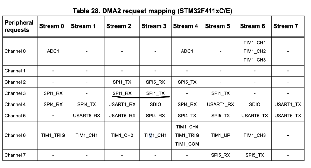
Since we require both TX and RX part, we shall use DMA2 Stream 2 and Stream 3 and channel 3 to handle the SPI communication
Hence, the DMA SPI Configuration as following:
Declare DMA_ConfigTypedef struct for SPI_TX as following:
DMA_ConfigTypedef SPI_TX_DMA;
Same thing for SPI_RX as following:
DMA_ConfigTypedef SPI_RX_DMA;
Declare two volatile variables for the interrupts which will works as flags in our application :
volatile uint8_t tx_finished=0,rx_finished;
Declare two arrays of size 7 to handle the two way communication:
uint8_t SPI_TX[7]={0x3B|0x80,0x00,0x00,0x00,0x00,0x00,0x00};

uint8_t SPI_RX[7];
In main function:
Configure the DMA_SPI_TX as following:
	SPI_TX_DMA.DMA_Channel=Channel3;
	SPI_TX_DMA.CircularMode=SingleTransfer;
	SPI_TX_DMA.MemorySize=byte;
	SPI_TX_DMA.PerpheralSize=byte;
	SPI_TX_DMA.MemoryIncMode=incMode;
	SPI_TX_DMA.PeripheralIncMode=SingleTransfer;
	SPI_TX_DMA.Direction=memory2Peripheral;
	SPI_TX_DMA.InterruptEnable=InterruptEnbaled;
	SPI_TX_DMA.TransferCompleteInterrupt=TransferComplet;
	SPI_TX_DMA.DMAStream=dma2stream3;
	BSP_DMA_Init(DMA2_Stream3, &SPI_TX_DMA);
For SPI_RX_DMA:
	SPI_TX_DMA.DMA_Channel=Channel3;
	SPI_TX_DMA.CircularMode=SingleTransfer;
	SPI_TX_DMA.MemorySize=byte;
	SPI_TX_DMA.PerpheralSize=byte;
	SPI_TX_DMA.MemoryIncMode=incMode;
	SPI_TX_DMA.PeripheralIncMode=SingleTransfer;
	SPI_TX_DMA.Direction=memory2Peripheral;
	SPI_TX_DMA.InterruptEnable=InterruptEnbaled;
	SPI_TX_DMA.TransferCompleteInterrupt=TransferComplet;
	SPI_TX_DMA.DMAStream=dma2stream3;
	BSP_DMA_Init(DMA2_Stream3, &SPI_TX_DMA);
They are identical except for the direction, the TX is memory to peripheral and RX peripheral to memory.
For interrupt handler:
void DMA2_Stream2_handler(void)
{
	if((DMA2->LISR & DMA_LISR_TCIF2)==DMA_LISR_TCIF2)
	{
		rx_finished=1;
	}

}


void DMA2_Stream3_handler(void)
{
	if((DMA2->LISR & DMA_LISR_TCIF3)==DMA_LISR_TCIF3)
	{
		tx_finished=1;
	}

}
Thats all for the DMA configuration.
2. Transfer Data from MPU9250 to STM32:
In while loop, we shall first prepare the RX buffer to hold the data to be received as following:
Start with setting cs pin to low:
GPIO_WritePin(GPIOA,&CS_Pin,Reset);
Prepare the rx buffer as following:
BSP_DMA_Transfer_Single_Buffer(DMA2_Stream2, (uint32_t)&SPI1->DR, (uint32_t)&SPI_RX,7);
Transmit data over SPI:
BSP_DMA_Transfer_Single_Buffer(DMA2_Stream3, (uint32_t)&SPI1->DR,(uint32_t)&SPI_TX,7);
Wait until the receive buffer is filled:
while(rx_finished ==0){;} Reset the rx flag:
rx_finished=0;
also, reset the tx flag:
if(tx_finished==1)tx_finished=0;
Set the cs pin to high:
GPIO_WritePin(GPIOA,&CS_Pin,Set);
Delay a little bit:
BSP_Delay(200);
Hence, the main.c code as following:
#include "bsp.h"
#include "uart_bsp.h"
#include "exti_bsp.h"
#include "bsp_debug.h"
#include "spi_bsp.h"
#include "dma_bsp.h"

#include "stdlib.h"

void clock_config(void);

volatile uint8_t tx_finished=0,rx_finished;


uint8_t SPI_TX[7]={0x3B|0x80,0x00,0x00,0x00,0x00,0x00,0x00};

uint8_t SPI_RX[7];


DMA_ConfigTypedef SPI_TX_DMA;

DMA_ConfigTypedef SPI_RX_DMA;


GPIO_Output_Typedef CS_Pin;


int main()
{


	#if FPU_EN
		SCB->CPACR |= ((3UL << 10*2)|(3UL << 11*2));
	#endif

	clock_config();
	BSP_Ticks_Init(100000000);

	GPIO_Configure_Typedef PA5_SPI,PA6_SPI,PA7_SPI;

	GPIOA_CLOCK_ENABLE();

	PA5_SPI.PinNumber=5;
	PA5_SPI.Mode=Alternate_function;
	PA5_SPI.AlternateType=AF5;
	PA5_SPI.OutPutspeed=High_Speed;


	PA6_SPI.PinNumber=6;
	PA6_SPI.Mode=Alternate_function;
	PA6_SPI.AlternateType=AF5;
	PA6_SPI.OutPutspeed=High_Speed;

	PA7_SPI.PinNumber=7;
	PA7_SPI.Mode=Alternate_function;
	PA7_SPI.AlternateType=AF5;
	PA6_SPI.OutPutspeed=High_Speed;

	GPIO_Initialization(GPIOA,&PA5_SPI);
	GPIO_Initialization(GPIOA,&PA6_SPI);
	GPIO_Initialization(GPIOA,&PA7_SPI);


	GPIO_Configure_Typedef CS_Pin_Config;

	CS_Pin_Config.PinNumber=pin0;
	CS_Pin_Config.Mode=OUTPUT;
	CS_Pin_Config.OutPutspeed=High_Speed;

	GPIO_Initialization(GPIOA,&CS_Pin_Config);

	GPIO_WritePin(GPIOA,&CS_Pin,Set);


	SPI_Enable_Clock(spi1);

	SPI_ConfigTypedef cSPI1;

	cSPI1.mode=Master_mode;
	cSPI1.slaveManagement=software_slave;
	cSPI1.baud=FCLK_32;
	cSPI1.CPHA=CPHA0;
	cSPI1.CPOL=CPOL0;
	cSPI1.LSBFirst=MSB_First;
	cSPI1.DMA_Enable=SPI_DMA_Enable;

	BSP_SPI_Config(SPI1,&cSPI1);


	__BSP_DMA2__CLOCK_ENABLE();

	SPI_TX_DMA.DMA_Channel=Channel3;
	SPI_TX_DMA.CircularMode=SingleTransfer;
	SPI_TX_DMA.MemorySize=byte;
	SPI_TX_DMA.PerpheralSize=byte;
	SPI_TX_DMA.MemoryIncMode=incMode;
	SPI_TX_DMA.PeripheralIncMode=SingleTransfer;
	SPI_TX_DMA.Direction=memory2Peripheral;
	SPI_TX_DMA.InterruptEnable=InterruptEnbaled;
	SPI_TX_DMA.TransferCompleteInterrupt=TransferComplet;
	SPI_TX_DMA.DMAStream=dma2stream3;
	BSP_DMA_Init(DMA2_Stream3, &SPI_TX_DMA);


	SPI_RX_DMA.DMA_Channel=Channel3;
	SPI_RX_DMA.CircularMode=SingleTransfer;
	SPI_RX_DMA.MemorySize=byte;
	SPI_RX_DMA.PerpheralSize=byte;
	SPI_RX_DMA.MemoryIncMode=incMode;
	SPI_RX_DMA.PeripheralIncMode=SingleTransfer;
	SPI_RX_DMA.Direction=peripheral2Memory;
	SPI_RX_DMA.InterruptEnable=InterruptEnbaled;
	SPI_RX_DMA.TransferCompleteInterrupt=TransferComplet;
	SPI_RX_DMA.DMAStream=dma2stream2;
	BSP_DMA_Init(DMA2_Stream2, &SPI_RX_DMA);


	while(1)
	{
		GPIO_WritePin(GPIOA,&CS_Pin,Reset);

		BSP_DMA_Transfer_Single_Buffer(DMA2_Stream2, (uint32_t)&SPI1->DR, (uint32_t)&SPI_RX,7);

		BSP_DMA_Transfer_Single_Buffer(DMA2_Stream3, (uint32_t)&SPI1->DR,(uint32_t)&SPI_TX,7);

		while(rx_finished ==0){;}

		rx_finished=0;

		if(tx_finished==1)tx_finished=0;

		GPIO_WritePin(GPIOA,&CS_Pin,Set);

		BSP_Delay(200);

	}
}

void clock_config(void)
{
	Clock_Config_Typedef clockConfig;

	clockConfig.PLL_M= 4;
	clockConfig.PLL_N= 200;
	clockConfig.PLL_P= 4;

	clockConfig.AHB1Prescaler=AHB1_Prescaler1;
	clockConfig.APB1Prescaler=APB1_Prescaler2;
	clockConfig.APB2Prescaler=APB2_Prescaler1;

	clockConfig.clockSourc=External_Oscillator;
	clockConfig.flash_latency= Three_wait_state;

	Clock_Configuration(&clockConfig);
}

void DMA2_Stream2_handler(void)
{
	if((DMA2->LISR & DMA_LISR_TCIF2)==DMA_LISR_TCIF2)
	{
		rx_finished=1;
	}

}


void DMA2_Stream3_handler(void)
{
	if((DMA2->LISR & DMA_LISR_TCIF3)==DMA_LISR_TCIF3)
	{
		tx_finished=1;
	}

}
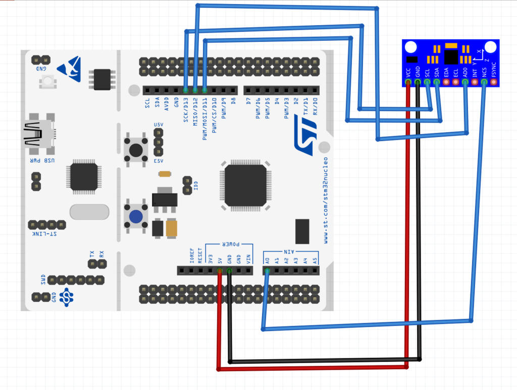
3. MPU9250 Connection:
The connection as following:
4. Results:
By adding SPI_RX buffer to live expression, we shall get the following:
That means, we have successfully transferred and received data over SPI bus using DMA.
Happy coding 🙂
Add Comment