
In the previous guide (here), we discussed how to send a single character using SPI in polling mode. This method will decrease the CPU performance since the CPU has to wait for each time before sending the character. In this guide, we shall introduce DMA to send number of byte without blocking the operation of the CPU.
In this guide, we shall discuss the following:
- Enable DMA in SPI
- Initialize the DMA
- Configure the DMA to send data
- Results
Note: in this guide, we will use STM32F407VGT. For another type of F4 series, you need to check the stream and channel.
1. Enable DMA for SPI:
The extra step needed to enable DMA_TX for SPI is to enable TXDMAEN bit in Control Register 2 (CR2)
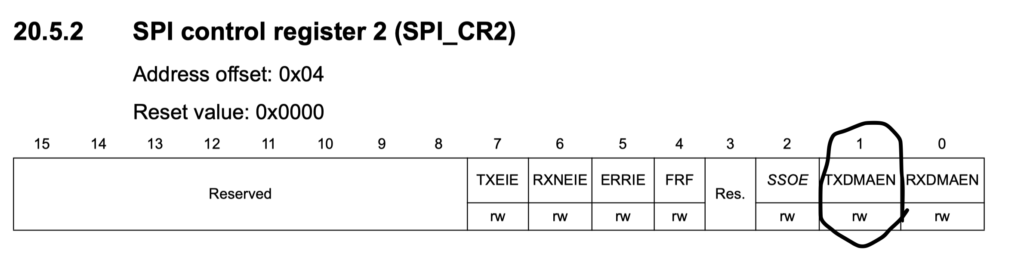
As following:
SPI1->CR2|=SPI_CR2_TXDMAEN;
Hence the initialization will be as following
/*
	* @brief initialize SPI1 peripheral and required pins
  * @param  None
  * @retval None

*/
void spi1_init(void)
		{
			//enable clock for GPIOA
		RCC->AHB1ENR|=RCC_AHB1ENR_GPIOAEN;
			//set PA5, PA6 and PA7 to alternate function mode
		GPIOA->MODER|=GPIO_MODER_MODE5_1|GPIO_MODER_MODE6_1|GPIO_MODER_MODE7_1;
			//set which type of alternate function is
		GPIOA->AFR[0]|=(0x05<<20)|(0x05<<24)|(0x05<<28);
			//enable clock access to SPI1
		RCC->APB2ENR|=RCC_APB2ENR_SPI1EN;
			//set software slave managment
		SPI1->CR1|=SPI_CR1_SSM|SPI_CR1_SSI;
			//set SPI in master mode
		SPI1->CR1|=SPI_CR1_MSTR;
		SPI1->CR1|=SPI_CR1_BR_0;
			//enable DMA_TX buffer
		SPI1->CR2|=SPI_CR2_TXDMAEN;
			//enable SPI peripheral
		SPI1->CR1|=SPI_CR1_SPE;


		}
2. 1 Initialize the DMA:
Before the Initializing, we need to know which Stream and Channel is Connected to SPI_TX
According the figure below, we have two options, either Stream 5 or Stream 3 and both on Channel 3.
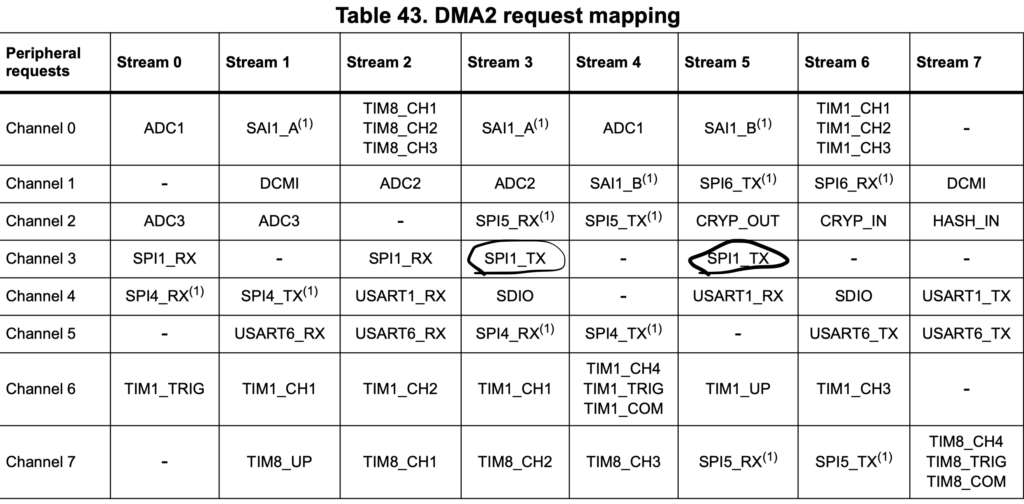
In our case, we shall use Stream 3.
We start off by enabling clock access to DMA2 as following:
RCC->AHB1ENR|=RCC_AHB1ENR_DMA2EN;
Then disable the stream and make sure it is disabled as following:
DMA2_Stream3->CR&=~DMA_SxCR_EN;
	while((DMA2_Stream3->CR)&DMA_SxCR_EN){;}
Set DMA2_Stream3 to for channel 3, increment the Memory, set direction from memory to peripheral and enable the following interrupts:
- Transfer Complete Interrupt
- Half transfer interrupt
- Transfer error interrupt
- Direct Mode error interrupt
#define ch3		(0x03<<25)
DMA2_Stream3->CR=ch3|DMA_SxCR_MINC|DMA_SxCR_DIR_0|DMA_SxCR_TCIE
	|DMA_SxCR_HTIE|DMA_SxCR_TEIE|DMA_SxCR_DMEIE;
Then we enable direct mode as following:
DMA2_Stream3->FCR&=~DMA_SxFCR_DMDIS;
Finally enable the interrupt in NVIC as following:
NVIC_EnableIRQ(DMA2_Stream3_IRQn);
Hence the initialisation will be as following:
/*
	* @brief intialize DMA2 Stream3 Channel 3
  * @param  None
  * @retval None

*/
void dma2_stream3_ch2_init(void)
	{
	RCC->AHB1ENR|=RCC_AHB1ENR_DMA2EN;
	DMA2_Stream3->CR&=~DMA_SxCR_EN;
	while((DMA2_Stream3->CR)&DMA_SxCR_EN){;}
	DMA2_Stream3->CR=ch3|DMA_SxCR_MINC|DMA_SxCR_DIR_0|DMA_SxCR_TCIE
	|DMA_SxCR_HTIE|DMA_SxCR_TEIE|DMA_SxCR_DMEIE;
	//DMA2_Stream3->FCR=0;
	DMA2_Stream3->FCR&=~DMA_SxFCR_DMDIS;
	NVIC_EnableIRQ(DMA2_Stream3_IRQn);

	}
2.2 DMA transfer setup
We start of by clearing all pending interrupts as following:
DMA2->LIFCR |=DMA_LIFCR_CTCIF3|DMA_LIFCR_CHTIF3|DMA_LIFCR_CTEIF3|DMA_LIFCR_CDMEIF3|DMA_LIFCR_CFEIF3;
Then set the peripheral address to SPI->DR as following:
DMA2_Stream3->PAR= (uint32_t)&SPI1->DR;
Set memory address to be the byte(s) to be sent as following:
DMA2_Stream3->M0AR=src;
Next we set how much data to be transferred as following:
DMA2_Stream3->NDTR=len;
Finally, we shall enable the DMA stream as following:
DMA2_Stream3->CR|=DMA_SxCR_EN;
Hence, the SPI transfer function using DMA shall be something like this:
/*
	* @brief initiation DMA transfer
  * @param  uint32_t src for data source
	* @param  uint32_t length of data source
  * @retval None

*/

	void spi_transfer_dma(uint32_t src,uint32_t len)
			{
				DMA2->LIFCR |=DMA_LIFCR_CTCIF3|DMA_LIFCR_CHTIF3|DMA_LIFCR_CTEIF3|DMA_LIFCR_CDMEIF3|DMA_LIFCR_CFEIF3;
				DMA2_Stream3->PAR= (uint32_t)&SPI1->DR;
				DMA2_Stream3->M0AR=src;
				DMA2_Stream3->NDTR=len;
				DMA2_Stream3->CR|=DMA_SxCR_EN;

			}
2.3 DMA interrupt handling
void DMA2_Stream3_IRQHandler(void)
		{

		if(DMA2->LISR&(DMA_LISR_TCIF3))
				{
					LED_PORT->ODR^=LED_blue;
					printf("finished transfered\r\n");
					finished=1;
					DMA2_Stream3->CR&=~DMA_SxCR_EN;
					DMA2->LIFCR |=DMA_LIFCR_CTCIF3;
				}

		if(DMA2->LISR&(DMA_LISR_HTIF3))
				{
					LED_PORT->ODR^=LED_green;
					printf("half transfered\r\n");
					DMA2->LIFCR |=DMA_LIFCR_CHTIF3;
				}


		if(DMA2->LISR&(DMA_LISR_TEIF3))
						{
						printf("transfer error interrupt\r\n");
						DMA2->LIFCR|=(DMA_LIFCR_CTEIF3);
						}

		if(DMA2->LISR&(DMA_LISR_DMEIF3))
						{
						printf("Direct mode interrupt error\r\n");
						DMA2->LIFCR|=(DMA_LIFCR_CDMEIF3);
						}

		if(DMA2->LISR&(DMA_LISR_FEIF3))
						{
						printf("FIFO error interrupt\r\n");
						DMA2->LIFCR|=(DMA_LIFCR_CFEIF3);
						}

			NVIC_ClearPendingIRQ(DMA2_Stream3_IRQn);
		}
2.4 Data to send
We will send the following characters:
char data[]={'A','B','C','D','E','F','G'};Which they should have the hex value from 0x41 to 0x47
In order to send the data using DMA we will use spi_transfer_dma as following:
spi_transfer_dma((uint32_t)data,sizeof(data));
			while(finished==0){} //wait untill data is transfered
			finished=0;
			delayMs(10);
2.5 Code Download:
You can download the entire code from here which is based on keil uVison IDE
3. Results:
Using Logic Analyzer and connecting D0 to PA5 and D2 to PA7 you shall get the following:
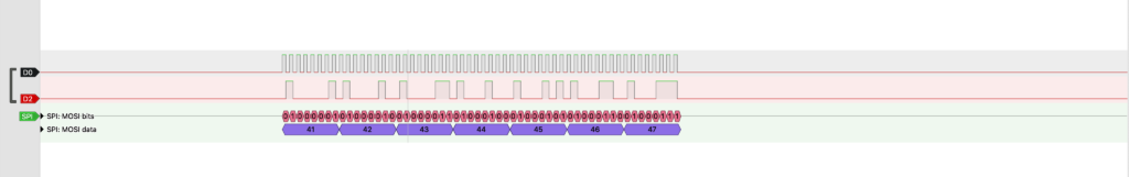
As you can see, we are getting the correct value 0x41, 0x42, 0x43, 0x44, 0x45, 0x46, 0x47
Add Comment