

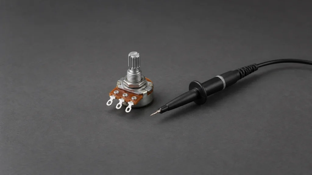
Building upon the basic single-conversion method, transitioning to continuous mode with interrupts unlocks a highly efficient, non-blocking approach to capturing analog data. This technique frees up the CPU to handle other critical tasks while the ADC autonomously converts the channel and only triggers an interrupt when fresh data is ready.
In this guide, we shall cover the following:
- Introduction.
- STM32CubeMX setup.
- Firmware development.
- Results.
1. Introduction:
In our previous exploration of the STM32F4’s Analog-to-Digital Converter, we utilized the Low Layer (LL) drivers to perform a single-channel, single-conversion read. While that method is incredibly fast and serves as an excellent introduction to bare-metal ADC mechanics, it relies on a polling approach. This means the CPU must sit idle in a loop, actively checking a status register, waiting for the conversion to finish. For simple, infrequent reads, this is perfectly acceptable. However, in complex, real-time embedded systems where CPU cycles are a precious commodity, tying up the processor to wait for an analog read is an inefficient use of resources.
To elevate our system’s efficiency, we must transition from a blocking architecture to a non-blocking one. This is achieved by combining two powerful features of the STM32F4 ADC: Continuous Conversion Mode and Interrupts.
The Evolution from Polling to Non-Blocking Design
When you enable Continuous Conversion Mode, the ADC undergoes a subtle but profound behavioral shift. Instead of performing a single conversion and halting until manually triggered again, the ADC autonomously restarts the conversion process the moment the previous one completes. It creates a relentless, continuous stream of analog data updates in the background.
However, if the ADC is constantly updating its data register, how does the CPU know when a new, valid piece of data is available without constantly polling? This is where Interrupts come into play.
By enabling the End-of-Conversion (EOC) interrupt, we instruct the ADC hardware to generate a hardware signal to the Nested Vectored Interrupt Controller (NVIC) the exact moment a conversion finishes and the data register is updated. When this interrupt fires, the CPU briefly suspends its current main-loop tasks, jumps to a dedicated Interrupt Service Routine (ISR) to grab the fresh data, and immediately resumes what it was doing.
Why Combine Continuous Mode with Interrupts?
The synergy of continuous mode and interrupts creates a highly elegant data acquisition pipeline:
- Zero CPU Wasted Cycles: The CPU is completely decoupled from the ADC’s conversion time. While the ADC is busy converting, the CPU can execute complex control algorithms, manage communication protocols, or update user interfaces.
- High-Frequency Data Streaming: This setup is ideal for applications that require a constant, high-frequency stream of analog data, such as digital signal processing (DSP), real-time audio sampling, or monitoring rapidly changing physical phenomena like motor current.
- Immediate Response: The latency between the ADC finishing a conversion and the CPU processing the data is minimized to the hardware interrupt response time, which on the Cortex-M4 core is a mere 12 clock cycles.
The LL Driver Advantage in Interrupts
Using the HAL library for continuous interrupt-driven ADC reads is notoriously heavy. The HAL interrupt handler (HAL_ADC_IRQHandler) performs a cascade of software checks, state updates, and callback resolutions before your code actually sees the data. In high-frequency continuous mode, this massive overhead can actually cause the system to crash or miss subsequent conversions because the CPU is still stuck inside the HAL interrupt handler when the next conversion finishes.
By utilizing the LL Drivers, we bypass this bottleneck entirely. We will directly configure the Continuous Mode bit, enable the EOC interrupt in the ADC registers, and write a lean, bare-metal ISR. When the interrupt fires, our ISR will execute in a fraction of the time, quickly reading the data register and clearing the interrupt flag, ensuring our system remains highly responsive and perfectly stable even under a relentless barrage of continuous analog data.
In the following sections, we will dive into the exact LL register configurations required to enable this mode, set up the NVIC, and implement the interrupt service routine that will seamlessly capture our analog data in the background.
Related course
Connect LL ADC conversion to interrupt handling
With the interrupt model established, explore the LL ADC and interrupt-driver foundations. Build a broader foundation in STM32 Low-Layer driver development. The course covers GPIO, UART, timers, ADC, interrupts, DMA, I2C and SPI, with a consistent approach to reading peripheral documentation and connecting configuration to working firmware.
2. STM32CubeMX Setup:
We shall continue from the previous guide from here.
From ADC configuration, set the Clock Prescaller to be divided by 8, set the continuous conversion to enabled as follows:
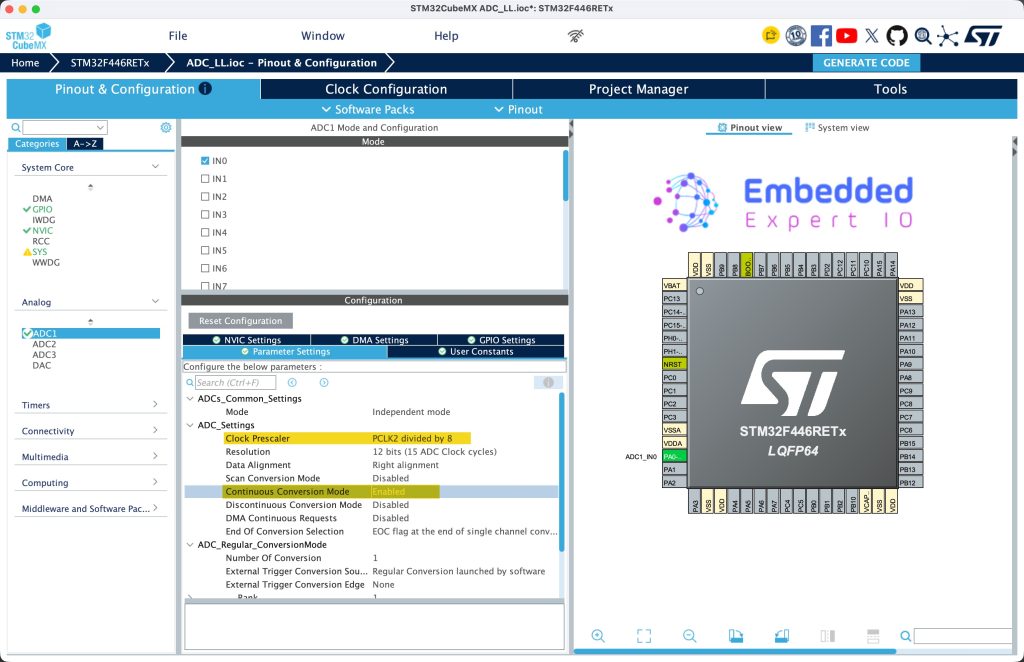
The reason behind reducing the clock is to reduce the interrupt rate. Since with each conversion, an interrupt is generated which will slow down the processor.
Next, from NVIC Settings, enable the interrupt for ADC1, ADC2 and ADC3 as follows:
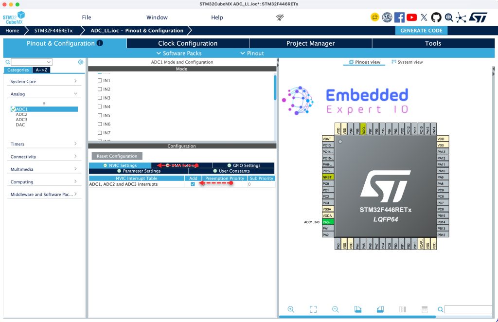
Note: STM32F446RE has three ADC while STM32F411 has single ADC.
Next, from System Core, NVIC, disable code generation for IRQ handler and click on Generate Code as follows:
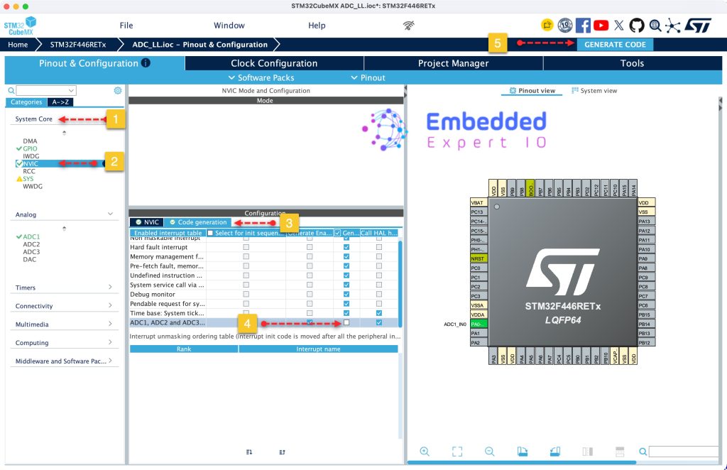
Thats all for the STM32CubeMX setup.
3. Firmware Development:
Open adc.h, in user code begin prototypes, declare the following functions:
uint8_t Is_Results_Ready(void);
This function shall return a flag that the ADC has finished conversion.
Next, a function that will clear the flag:
void Clear_ADC_Ready(void);
Next, function to read the converted ADC:
uint16_t Read_ADC_Results(void);
Finally, start the ADC in interrupt mode as follows:
void ADC_Cont_IT_Start(void);
Thats all for the header file.
Next, open adc.c file.
In user code begin 0, declare the following:
volatile uint8_t adc_ready;
This is the flag which will be set in the interrupt to indicate that the conversion is completed.
volatile uint16_t adc_result;
This will hold the measured adc value.
Next, in user code begin 1 in adc.c.
For Is_Results_Ready function:
uint8_t Is_Results_Ready(void)
{
	return adc_ready;
}
Clear the flag function:
void Clear_ADC_Ready(void)
{
	adc_ready=0;
}
Read the measured ADC value:
uint16_t Read_ADC_Results(void)
{
	return adc_result;
}
As for starting the ADC in interrupt mode:
void ADC_Cont_IT_Start(void)
{
	adc_ready=0;

	LL_ADC_EnableIT_EOCS(ADC1);   // enable ADC EOC interrupt
	LL_ADC_Enable(ADC1);          // enable ADC
	LL_ADC_REG_StartConversionSWStart(ADC1); // start conversion
}
As for the ADC interrupt handler:
void ADC_IRQHandler (void)
{
	if (LL_ADC_IsActiveFlag_EOCS(ADC1))
	{
		adc_result = LL_ADC_REG_ReadConversionData12(ADC1);
		adc_ready = 1;

		LL_ADC_ClearFlag_EOCS(ADC1);
	}
}
Thats all for the adc.c source file.
Next, open main.c
In user code begin 2 in main function, start the ADC in interrupt mode as follows:
ADC_Cont_IT_Start();
In while 1 loop in user code begin 3:
if(Is_Results_Ready()==1)
{
  adc_value=Read_ADC_Results();
  Clear_ADC_Ready();
}- Check if the conversion is completed.
- Read the current value.
- Clear the flag.
Thats all for the firmware.
Save, build the project and run it as follows:

You may download the project from our github repository from here.
4. Results
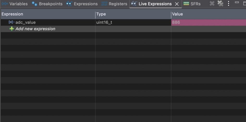
Open a debugging session, add adc_value to live expression, you should get something like this:
Thats all for the guide.
Next, we shall use interrupt to acquire ADC from multiple channels.
Stay tuned.
Happy coding 😉
\
Discussion