This guide demonstrates how to configure the STM32F4 Analog-to-Digital Converter (ADC) using the Low Layer (LL) drivers for a straightforward single-channel, single-conversion read. By bypassing the overhead of the Hardware Abstraction Layer (HAL), this approach provides a lightweight, direct, and highly efficient method for reading analog sensor data.
In this guide, we shall cover the following:
- Introduction.
- STM32CubeMX setup.
- Importing the project to STM32CubeIDE.
- Firmware development.
- Results.
1. Introduction:
In the world of embedded systems, bridging the gap between the analog physical world and the digital processing domain is a fundamental task. Whether you are reading a temperature sensor, monitoring a battery voltage, or capturing audio, the Analog-to-Digital Converter (ADC) is your gateway. The STM32F4 family of microcontrollers, renowned for its powerful Cortex-M4 core and rich peripheral set, features a highly sophisticated ADC capable of speeds up to 2.4 MSPS. However, the way you choose to software-interface with this ADC can drastically alter the performance, memory footprint, and predictability of your application.
When programming STM32 microcontrollers, developers typically stand at a crossroads: choosing between the Hardware Abstraction Layer (HAL) or the Low Layer (LL) drivers. Both libraries are provided by STMicroelectronics and can be generated via STM32CubeMX, but they cater to distinctly different engineering philosophies.
The Great Debate: HAL vs. LL Drivers
The Hardware Abstraction Layer (HAL) is designed with portability and ease of use in mind. It provides a high-level, user-friendly API that hides the complex register manipulations beneath the surface. If you write a piece of code using HAL for the STM32F4, porting that code to an STM32L4 or STM32G4 requires minimal changes.
- Pros: HAL significantly reduces development time. It handles edge cases, initialization states, and complex sequences (like DMA multi-channel scans) out-of-the-box. It is ideal for rapid prototyping, beginners, and applications where time-to-market is more critical than raw silicon-level efficiency.
- Cons: This convenience comes at a cost. The HAL introduces significant overhead. A simple ADC read involves multiple function calls, state-checking variables, and timeout mechanisms. This overhead consumes more Flash memory, utilizes more RAM, and introduces latency, which can be detrimental in strict real-time or resource-constrained applications.
The Low Layer (LL) Drivers, on the other hand, offer a lightweight, optimized alternative. The LL drivers sit just a thin step above direct register-level programming. They provide inline functions and macros that map almost directly to the microcontroller’s hardware registers.
- Pros: LL code is incredibly fast and highly deterministic. Because it strips away the bloated state-checking and abstract logic of the HAL, it executes in a fraction of the clock cycles. It also consumes minimal memory, making it perfect for bootloaders, interrupt service routines (ISRs), ultra-low-power applications, and high-frequency control loops.
- Cons: The trade-off is portability and readability. LL code is highly specific to the exact microcontroller family you are using. An LL configuration for an STM32F4’s ADC will not directly translate to an STM32F1. Furthermore, it requires the developer to have a much deeper understanding of the microcontroller’s Reference Manual, as you are dealing much closer to the bare metal.
Why LL for a Single-Channel, Single-Conversion Read?
For a task as fundamental as reading a single analog channel in a one-shot conversion, using the HAL can feel like using a sledgehammer to crack a nut. The overhead of the HAL’s HAL_ADC_Start() and HAL_ADC_PollForConversion() functions introduces unnecessary cycles that delay your execution.
By utilizing the LL drivers for this task, we achieve a lean, highly efficient read. We will directly enable the ADC, trigger the conversion, poll the status register, and read the data register in a fraction of the time it takes HAL to do the same. This approach not only saves valuable program memory but teaches you exactly what is happening under the hood of the STM32F4’s ADC peripheral.
2. STM32CubeMX Setup:
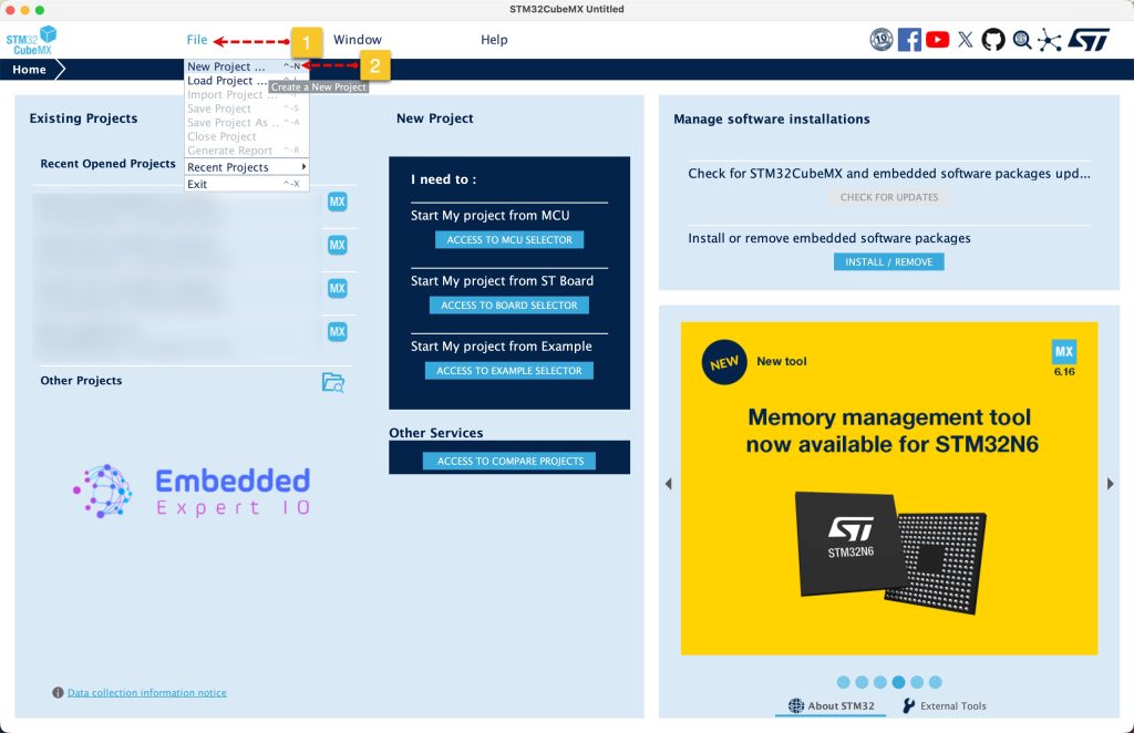
Open STM32CubeMX as start a new project as follows:
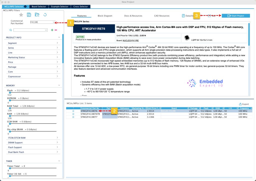
Search for your STM32 MCU, select the MCU and click on Start New Project as follows:
Next, from Analog, ADC1, select IN0 as input:
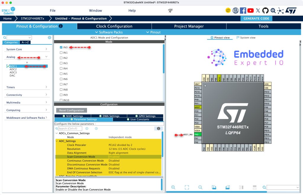
This will enable PA0 as analog input.
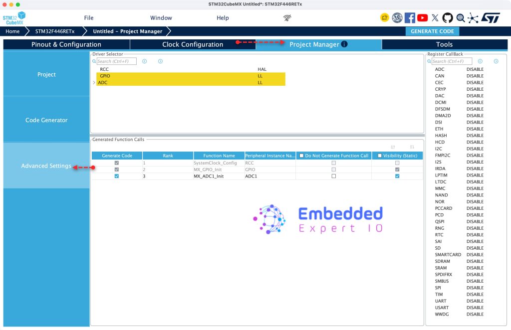
Next, from Project Manager, Advanced Settings, set GPIO and ADC as LL, keep RCC as HAL, we shall use the delay.
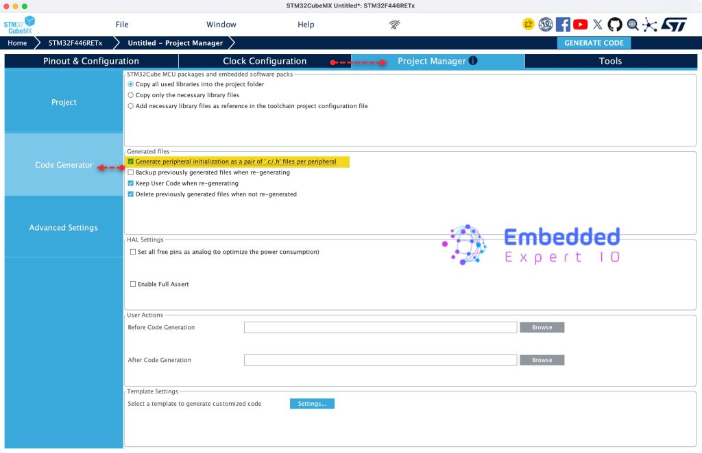
Next, from Code Generation, enable generation peripheral initialization as pair of .c/h per peripheral as follows:
Finally, from Project, Give the project a name, set toolchain/IDE to STM32CubeIDE and click Generate Code as follows:
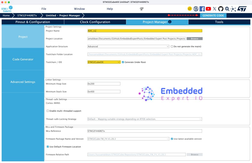
That’s all for STM32CubeMX configuration.
3. Importing the Project to STM32CubeIDE:
Open STM32CubeIDE, select your workspace and click on Launch.
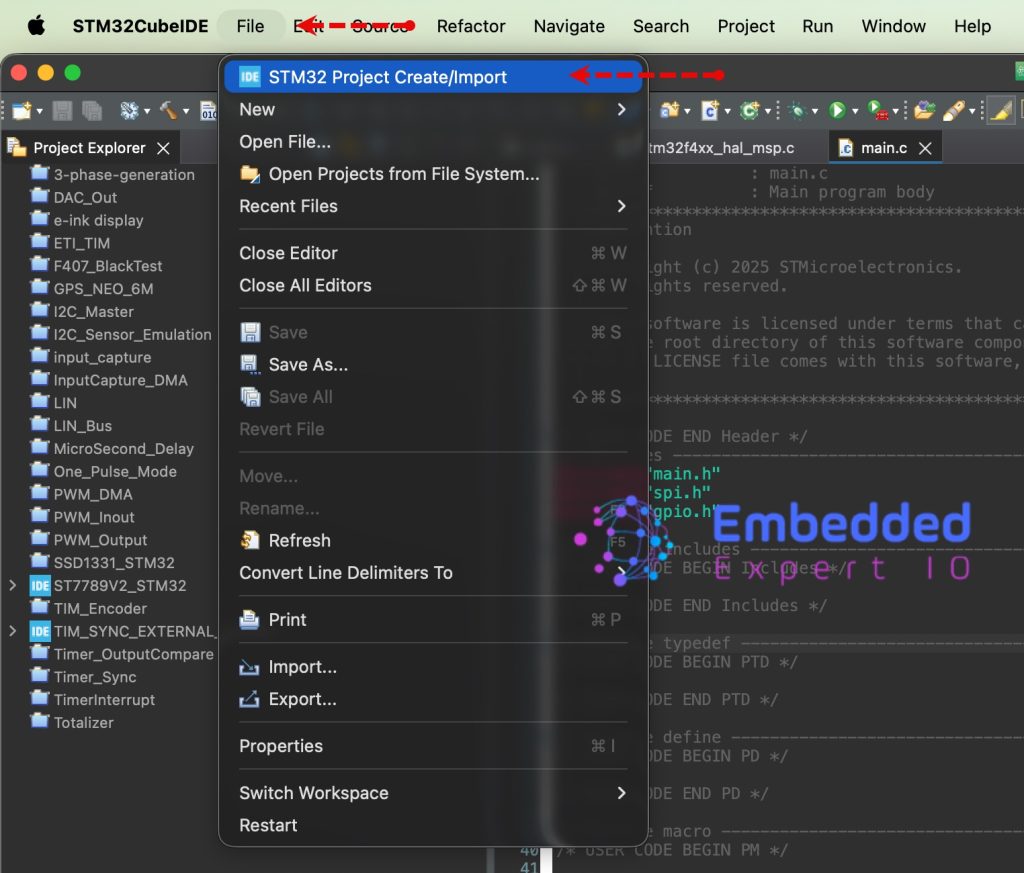
From the IDE, click File and select STM32 Project Create/Import as follows:
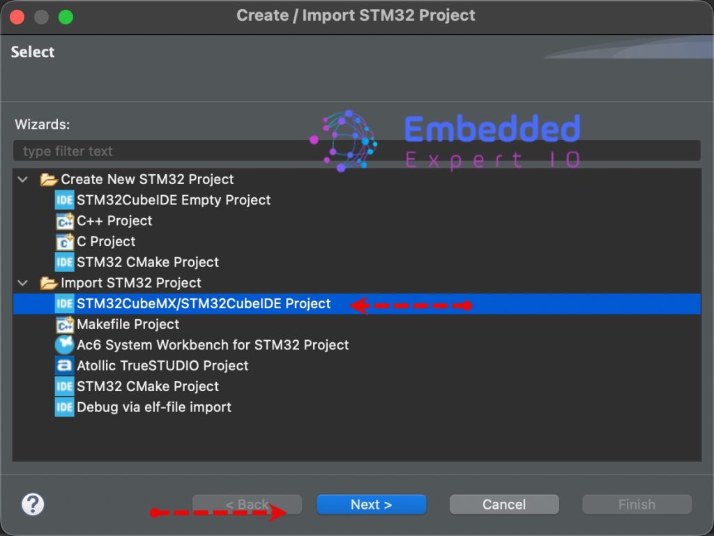
Next, from Import STM32 Project, select STM32CubeMX/STM32CubeIDE Project and click on Next as follows:
Next, select the folder that contains the .ioc file and click on Finish as follows:
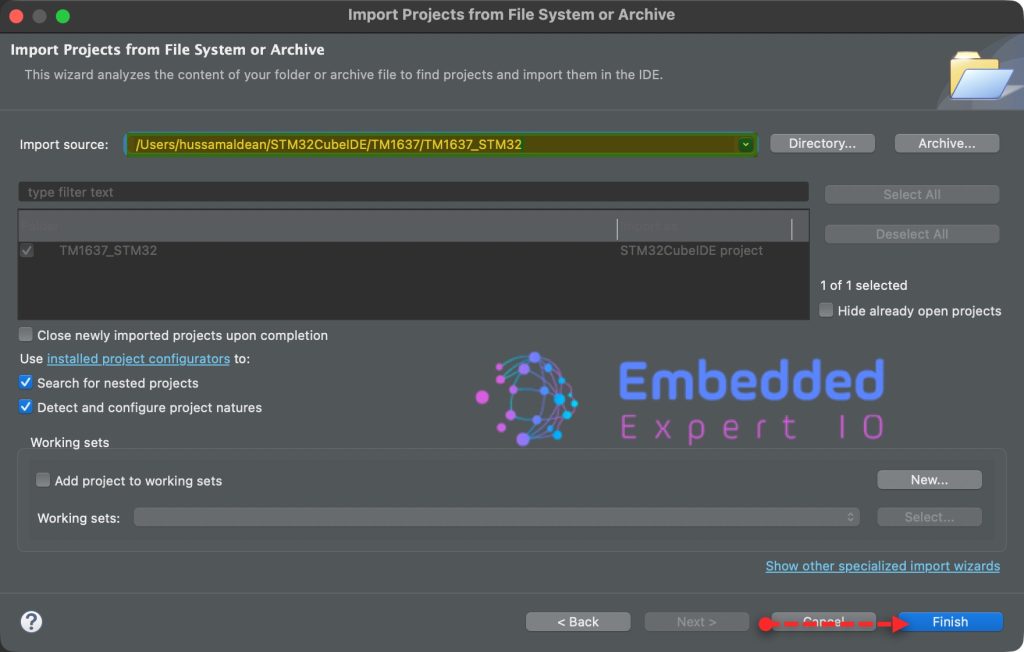
Note: Project name is for reference only.
4. Firmware Development:
Open adc.h header file and in user code begin prototype, declare the following function:
uint16_t ADCReadBlocking(void);
This function shall read the ADC in blocking mode and return the measured ADC value.
Next, open adc.c and in user code begin 1, we shall populate the function.
We start by declaring the ADCReadBlocking function as follows:
uint16_t ADCReadBlocking(void)
Within the function, we start by enabling the ADC as follows:
/* Enable the ADC */
LL_ADC_Enable(ADC1);
Next, start the conversion using software trigger:
/* Start conversion */
LL_ADC_REG_StartConversionSWStart(ADC1);
Next, wait for the conversion to complete as follows:
/* Wait for end of conversion */
while (!LL_ADC_IsActiveFlag_EOCS(ADC1));
Next, read the result of the conversion as follows:
/* Read ADC value */
uint16_t val = LL_ADC_REG_ReadConversionData12(ADC1);
Disable the ADC:
/* Disable the ADC */
LL_ADC_Disable(ADC1);
Finally, return the measured value as follows:
return val;
Hence, the function as follows:
uint16_t ADCReadBlocking(void)
{
	/* Enable the ADC */
	LL_ADC_Enable(ADC1);

	/* Start conversion */
	LL_ADC_REG_StartConversionSWStart(ADC1);

	/* Wait for end of conversion */
	while (!LL_ADC_IsActiveFlag_EOCS(ADC1));

	/* Read ADC value */
	uint16_t val = LL_ADC_REG_ReadConversionData12(ADC1);

	/* Disable the ADC */
	LL_ADC_Disable(ADC1);

	return val;
}
Next, in main.c file.
In user code begin PV, declare the following variable:
uint16_t adc_value;
This will hold the measured adc value.
Next, in user code begin 3 in while 1 loop, start the conversion each 200ms as follows:
adc_value=ADCReadBlocking();
HAL_Delay(200);
Thats all for the firmware.
Save, build the project and run it as follows:

You may download the project from our github repository from here.
5. Results
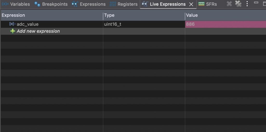
Open a debugging session, add adc_value to live expression, you should get something like this:
Thats all for the guide.
Next, we shall use continuous mode with interrupt to keep the ADC data alive.
Stay tuned.
Happy coding 😉

Add Comment