In this second part of creating UI using LvGL and EEZ Studio, we shall see how to communicate between the UI and the MCU by controlling the LED using the switch and update the bar.
In this guide, we shall cover the following:
- Configure the UI.
- Configure the LED.
- Update bar and LED control
- Results.
6. Configure the UI:
We start off by opening screens.c source from the ui folder as following:
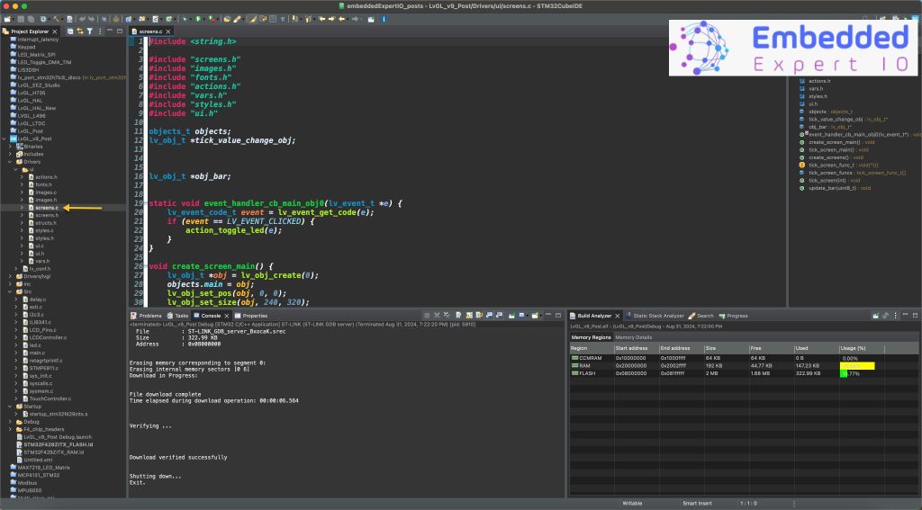
Next declare the following variable as global:
lv_obj_t *obj_bar;
In the section where the bar is created by the EEZ Studio, we need to modify it as following:
        	obj_bar = lv_bar_create(parent_obj);
            lv_obj_set_pos(obj_bar, 45, 183);
            lv_obj_set_size(obj_bar, 150, 10);
            lv_bar_set_value(obj_bar, 25, LV_ANIM_OFF);
This way, the bar object is available globally and can be accessed any time.
At the end of the screens.c declare the following function:
void update_bar (uint8_t value)
{
	lv_bar_set_value(obj_bar,value,LV_ANIM_OFF);
}
The function shall update the bar value.
It takes value as argument.
The lv_bar_set_value takes the following arguments:
- Bar object which obj_bar in this case.
- Value to be updated.
- Animation on or off.
Next, open screens.h as following:
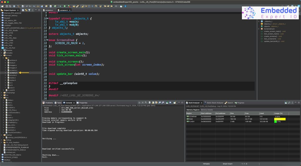
At the end before #ifend __cplusplus, add the following function:
void update_bar (uint8_t value);
Now, we have access to the update function.
7. LED Configuration:
Since STM32F429-disco features two leds connected to PG13 and PG14. We shall use PG13 as our LED to be controlled.
Create new source and header file with name of led.c and led.h.
The header file content:
#ifndef LED_H_
#define LED_H_
#include "stdint.h"

void led_init(void);
void write_led(uint8_t state);


#endif /* LED_H_ */
For led source file:
#include "stm32f4xx.h"

#include "led.h"

void led_init(void)
{
	RCC->AHB1ENR|=RCC_AHB1ENR_GPIOGEN;

	GPIOG->MODER|=GPIO_MODER_MODE13_0;

	GPIOG->MODER&=~GPIO_MODER_MODE13_1;

}

void write_led(uint8_t state)
{
	if(state==1)
	{
		GPIOG->BSRR=GPIO_BSRR_BS13;
	}
	else
	{
		GPIOG->BSRR=GPIO_BSRR_BR13;
	}
}
8. Update Bar and LED Control:
In main.c file, first include the led header file as following:
#include "led.h"
Declare the following three variables as following:
uint8_t value;
uint8_t dir=0;
uint32_t previous;
First variable is the value to be passed to update the bar.
Dir which is the direction either the value increment or decrement.
Previous which is used to store the previous time in milliseconds.
before he initialization of the UI, initialize the led as following:
led_init();
Store the current run time in the previous variable:
previous=millis();
In the while 1 loop after the ui_tick():
if(millis()-previous>10)
		{
			if(dir==0)
			{
				value++;
				if(value==100)
				{
					dir=1;
				}
			}
			if(dir==1)
			{
				value--;
				if(value==0)
				{
					dir=0;
				}
			}


			update_bar(value);
			previous=millis();
		}
This will update the value each 10 milliseconds in none blocking mode.
Finally the previous declared led toggle function:
void action_toggle_led(lv_event_t * e)
{
	lv_event_code_t code = lv_event_get_code(e);
	lv_obj_t * obj = lv_event_get_target(e);
	uint8_t state=lv_obj_has_state(obj,LV_STATE_CHECKED);
	write_led(state);

}
Get the code of the even.
Get the object which trigger the even.
Get the of the object which is in this case is switch.
Pass the state to the write_led to turn on/off according to switch state.
Save the project, build it and run it on your STM32F429-Disco.

9. Results:
Notice that the bar is being updated and when the switch is clicked, the LED state changes as we intended.
Happy coding 😉
Add Comment