

This guide walks through configuring an STM32F4 timer in PWM mode with DMA-driven duty cycle updates, using the STM32CubeMX-generated initialization and STM32 LL drivers to stream a sine wave lookup table directly into the capture/compare register. By the end, you’ll have a clean, reusable setup that produces a stable 50 Hz sine wave from a 10 kHz PWM carrier — and a foundation you can retarget to any timer, channel, or waveform.
In this guide, we shall cover the following:
- Introduction.
- STM32CubeMX setup.
- Firmware development.
- Results.
1. Introduction:
The problem: why waveform generation is harder than it looks
Generating a precise, repeatable analog waveform from a digital microcontroller is one of those tasks that appears trivial on paper — “just update the duty cycle in a loop” — but falls apart the moment you try to do it properly in a real embedded system. The naive approach is to write new compare values into the timer’s capture/compare register from software, typically inside a timer interrupt that fires once per PWM period. This works, and for a hobby project blinking an LED at a leisurely 2 Hz, it works fine. But the moment you need the waveform to be clean — meaning every period has the exact same width, every sample lands at the exact same instant, and the output does not visibly twitch when unrelated code runs — the software-timed approach reveals its weaknesses in three distinct ways.
First, there is jitter. A timer interrupt does not fire at a perfectly deterministic instant. It fires when the timer counter rolls over, yes, but the CPU may be in the middle of a higher-priority interrupt, may have interrupts briefly masked by a critical section, may be executing a multi-cycle floating-point instruction that delays the ISR entry, or may be stalled on a flash access. Each of these adds a few cycles of uncertainty to when the ISR actually runs and therefore to when the CCR register is actually written. At 10 kHz PWM, one period is 100 µs — a few hundred nanoseconds of jitter is already 0.2–0.5% of the period, and that jitter shows up directly as phase noise in whatever waveform you are synthesizing. At audio frequencies this is audible as a harsh, “dirty” tone rather than a clean sine; in motor control it manifests as current ripple and acoustic noise; in precision instrumentation it corrupts the measurement.
Second, there is CPU load. A 200-sample sine wave at 50 Hz means a timer interrupt every 100 µs, forever, whether the CPU is busy or idle. Each interrupt costs — conservatively — 30 to 60 cycles just in context save/restore plus the actual work of reading the next sample and writing it into the CCR register. At 100 µs per interrupt and a 100 MHz core, that is only 10,000 cycles per period, so the ISR eats 0.3–0.6% of the CPU. That sounds cheap, until your project grows and you have four timers doing this, plus USB, plus an ADC sampling loop, plus a control loop, plus a filesystem write. Suddenly the “cheap” PWM updates are competing for cycles with real work, and if the scheduler has a hiccup, the waveform degrades.
Third, there is the code fragility problem. An interrupt-driven waveform generator implies an interrupt handler, which implies shared state between the ISR and the main loop, which implies the usual parade of embedded bugs: a flag that gets cleared at the wrong time, a buffer that gets overwritten while the ISR reads from it, a state machine that gets out of sync after a missed interrupt, a subtle race that only appears once every ten thousand cycles. None of this is insurmountable, but all of it is unnecessary — because the hardware offers a better path.
The solution: let hardware do what hardware is good at
The STM32 timer peripherals were designed to solve exactly this problem. A general-purpose or advanced timer like TIM2 is not just a counter — it is a small, self-contained state machine that can count, compare, toggle outputs, generate events, and request DMA transfers without any CPU involvement whatsoever. When you combine a timer running in PWM mode with a DMA controller running in circular mode, and point the DMA at a lookup table sitting in SRAM, you get a waveform generator that is:
- Jitter-free, because the DMA transfer is triggered by the timer’s own compare event — an on-chip signal with a delay measured in nanoseconds, not in interrupt latency.
- CPU-free, because once the DMA is armed and the timer is started, not a single instruction runs until you decide to stop it. The CPU is free to do anything — sleep, compute, handle USB, run a control loop — and the waveform does not notice.
- Deterministic, because the DMA reads sequentially from a fixed buffer with a fixed stride, so the sequence of duty cycles applied to the PWM output is precisely the sequence stored in memory, with no possibility of a sample being skipped or repeated.
- Scalable, because the same pattern works for one timer or eight, for 200 samples or 200,000, for a sine wave or a chirp or a piecewise-linear motor commutation sequence — the mechanism does not change.
- Simple in code, because the entire waveform generator collapses to a handful of register writes at startup, plus one interrupt if you want to know when the buffer has wrapped.
This is not a trick or a workaround — it is the intended use case of the timer and DMA peripherals, the reason they have the interconnectivity features they do, and the pattern that ST’s own reference manuals and application notes present as the correct way to generate arbitrary waveforms at high update rates. The STM32F4 family is especially well-suited to it: its timers are 32-bit on TIM2 and TIM5, its DMA controllers support memory-to-peripheral transfers with configurable data widths, and its DMA request mapping lets any timer’s update, compare, or trigger event drive a DMA channel directly.
What this guide builds, and why each piece matters
The concrete goal of this guide is modest: produce a stable 50 Hz sine wave on a single PWM pin, using a 10 kHz PWM carrier, with the duty cycle updated 200 times per period by DMA from a lookup table in SRAM. But every design decision along the way generalizes.
The PWM carrier is the timer’s output signal before any modulation is applied — a fixed-frequency square wave whose duty cycle is set by the compare register. Choosing the carrier frequency is a trade-off: higher carrier means finer time resolution and easier filtering but more switching losses in any downstream power stage and more DMA traffic; lower carrier means less overhead but a coarser sample grid. 10 kHz is a reasonable middle ground for an F4 running at 16 MHz: the PWM period is (1600 + 1) ticks at 16 MHz, which is 100 µs, giving a 10 kHz carrier and a 200-sample sine period of 20 ms, or 50 Hz.
The lookup table is the heart of the generator — a precomputed array of compare values that, when applied in sequence, trace out the desired waveform. For a sine wave it is simply (sin(2πi/N) + 1) / 2 * ARR, rounded to integers. The table is symmetric and periodic, so the same 200 values repeat forever, which is exactly what circular DMA wants. The table’s length determines the relationship between the carrier frequency and the output frequency: f_out = f_carrier / N. Changing the output frequency is as simple as changing N, or as simple as changing the timer’s prescaler — the table itself is unchanged.
The DMA stream is configured once, at startup, to read successive halfwords from the table and write them into the timer’s CCR1 register. The critical subtlety is the DMA request source: it must be the timer’s CC1 compare event, not the update event, because CC1 fires when the timer counter matches CCR1 — exactly the moment the new compare value should be latched. The second critical subtlety is CCR preload: the timer must have its output compare preload bit enabled so that a write to CCR1 during an active period takes effect at the next period boundary, not immediately (which would corrupt the current pulse). Both of these are set by CubeMX if you configure the timer correctly, and both are essential to producing a glitch-free waveform.
The circular mode of the DMA is what makes the whole thing run indefinitely without CPU attention. In normal mode, the DMA performs N transfers and stops, and the CPU must re-arm it at the end of every period — which defeats the purpose. In circular mode, the DMA hardware automatically resets its internal transfer counter when it reaches the end of the buffer and starts over, forever, without touching memory management or interrupt state. This is the single design choice that turns a one-shot burst into a continuous waveform generator.
Applications: where this pattern shows up in the real world
The reason this pattern is worth learning — and worth doing correctly rather than hacking together with an ISR — is that it appears, in nearly identical form, at the heart of an enormous number of real embedded systems. A short survey:
Motor control. Brushless DC (BLDC) and permanent-magnet synchronous motors (PMSM) require three sinusoidal drive signals, each phase-shifted by 120°, whose amplitude and frequency track the rotor position. The standard approach — field-oriented control (FOC) — computes the desired phase voltages in software at a modest rate (typically a few kHz), then hands them to a timer+DMA subsystem that produces the actual PWM at 20–100 kHz. The DMA-driven approach guarantees that the three phases remain precisely synchronized, that no PWM cycle is ever missed or widened due to interrupt latency, and that the CPU is free to run the FOC math and the position observer without being preempted by the waveform generator. Any distortion in the drive waveform produces torque ripple, audible noise, and reduced efficiency — the motor “growls” — and a jittery software-timed update is one of the most common causes.
LED lighting and displays. Visible-light LED dimming needs to happen above roughly 1 kHz to avoid flicker, and it needs the duty cycle to follow a perceptual curve rather than a linear one — human vision is roughly logarithmic, so a linear duty ramp looks like it does nothing for the first half and then slams to full brightness in the last few percent. The standard fix is a gamma-corrected lookup table, applied via the same timer+DMA pattern as this guide. The same technique scales to LED matrix displays, RGB color mixing, and theatrical lighting, where hundreds of channels must each follow an independent (often pre-programmed) curve with sub-millisecond synchronization.
Audio and signal generation. A timer in PWM mode plus a low-pass filter (an RC network, sometimes followed by an op-amp buffer) is the cheapest way to generate an analog signal from a digital pin — it is functionally a one-bit DAC oversampled at the carrier frequency. For audio tones, function generators, DTMF dialing, ultrasonic transducers, and simple music synthesis, this is often the right answer: 10 kHz carrier, 200-sample table, and a first-order or second-order LPF gives you a recognizable — if not high-fidelity — sine or square or triangle wave for the cost of one timer and one filter. More sophisticated audio applications push the carrier into the hundreds of kHz and use higher-order filters or delta-sigma modulation, but the underlying timer+DMA mechanism is exactly the same.
Power electronics. Sine-wave inverters — the kind used in solar installations, uninterruptible power supplies, and variable-frequency drives — must synthesize a clean 50 Hz or 60 Hz sine wave at high power. The reference waveform is generated by the microcontroller (using this exact pattern), then compared against a high-frequency triangle carrier to produce the PWM that drives the power switches; the resulting output, after filtering, should be a near-perfect sine. Distortion in the reference waveform translates directly into harmonic content in the output, which stresses transformers, trips sensitive loads, and violates grid codes. Hardware-timed generation with a clean lookup table is not optional at this scale — it is the difference between a working inverter and one that trips breakers.
Test and measurement. Signal generators, arbitrary waveform generators, and stimulus sources for sensor testing all use this pattern. The lookup table becomes a “waveform” stored in memory — a sine, a chirp, a pseudo-random noise sequence, a recorded physiological signal — and the timer+DMA machinery plays it back with sample-accurate timing. The ability to swap waveforms by simply pointing the DMA at a different buffer, and to change the playback rate by changing the timer prescaler, makes this a highly flexible architecture for instrumentation.
Sensor simulation and HIL testing. In hardware-in-the-loop (HIL) test benches, a microcontroller is often called upon to simulate the analog output of a sensor — a throttle position sensor, a wheel speed sensor, a pressure transducer — while the device under test believes it is talking to the real thing. This is the same PWM+DMA+filter pattern: precomputed waveform tables for each simulated condition, selected by the test harness, played back through a timer.
Clock and timing generation. A timer in toggle mode or PWM mode, driven by DMA, can generate precise periodic signals for clocking external ADCs, synchronizing multiple boards, driving stepping motors, or producing a reference frequency for a PLL. The precision here comes from the timer’s own clock, not from the CPU, so the frequency is exact to the timer’s resolution and does not vary with software load.
What you will have at the end
By the end of this guide you will have a complete, working, reusable subsystem: a timer configured for PWM, a DMA stream configured for circular memory-to-peripheral transfer, a lookup table of 200 sine samples, and a single function that starts the whole thing with one call. The waveform on the pin will be a 50 Hz sine wave riding on a 10 kHz PWM carrier, ready to be filtered into a clean analog signal or fed directly into a motor driver or an LED.
More importantly, you will understand why each piece is configured the way it is — why the DMA request source is CC1 and not UPDATE, why the CCR preload bit must be enabled, why circular mode matters, why the lookup table length determines the output frequency, why the buffer type must match the DMA data width, and why the whole arrangement is more robust than the interrupt-driven alternative. That understanding is what lets you take the pattern and apply it to the next problem: a different timer, a different waveform, a different frequency, a different number of channels — the mechanics stay the same, and you will have the mental model to configure it correctly the first time.
2. STM32CubeMX setup:
We shall continue from this guide here.
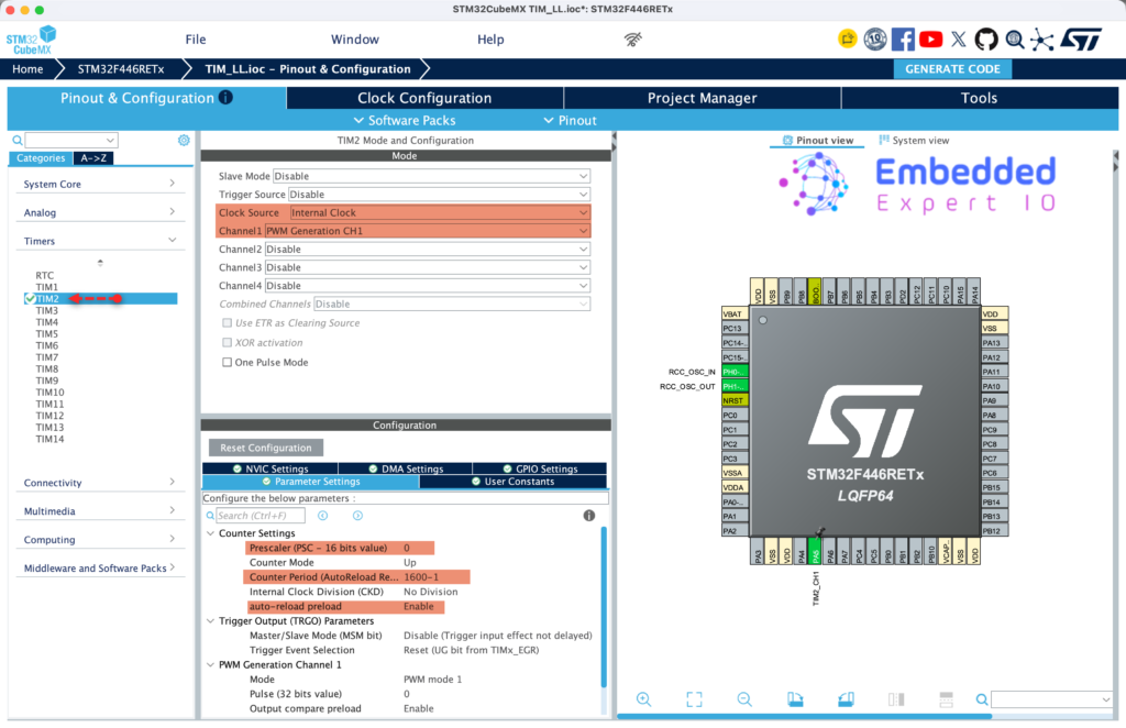
From TIM2, set the prescaler to 0 and set the timer period to 1600-1 with autoreload preload is enabled as follows:
Next, from the DMA settings, enable the DMA and set it as follows:
- Direction is Memory to Peripheral.
- Mode set to Circular.
- Data Width to Word.
Please note that if you used 16-bit timer, you need to set the data width to half-word.
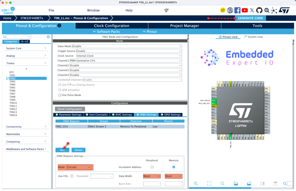
Finally, click on Generate Code.
Thats all for the STM32CubeMX setup.
3. Firmware Development:
Open the project in STM32CubeIDE.
Open the tim.h
In user code begin prototypes, declare the following function:
void PWM_DMA_Start(uint32_t *buffer, uint32_t length);
This function stall start the PWM in DMA mode and takes the following two parameters:
- Pointer to the buffer that holds the duty cycles values.
- Size of the buffer.
Next, in tim.c source file, USER CODE BEGIN TIM2_Init 2 in MX_TIM2_Init function, add the following two lines:
  TIM_InitStruct.Autoreload = 1600;
  LL_TIM_Init(TIM2, &TIM_InitStruct);
This will ensure that the period is 1600-1 as we need. This is due to bug in the generation of timer period in STM32CubeMX.
Next, in user code begin 1 in tim.c:
Declare the PWM DMA function:
void PWM_DMA_Start(uint32_t *buffer, uint32_t length)
Within the function, setup the DMA:
/* Point the DMA stream at TIM2->CCR1 and at the user buffer */
	LL_DMA_SetPeriphAddress(DMA1, LL_DMA_STREAM_5, (uint32_t)&TIM2->CCR1);
	LL_DMA_SetMemoryAddress(DMA1, LL_DMA_STREAM_5, (uint32_t)buffer);
	LL_DMA_SetDataLength(DMA1,    LL_DMA_STREAM_5, length);
Next, enable DMA request to CC1 of TIM2 as follows:
LL_TIM_EnableDMAReq_CC1(TIM2);
Next, enable the DMA stream:
LL_DMA_EnableStream(DMA1, LL_DMA_STREAM_5);
Next, start the timer in PWM mode as follows:
	LL_TIM_CC_EnableChannel(TIM2, LL_TIM_CHANNEL_CH1);
	LL_TIM_EnableCounter(TIM2);
Load the first CCR value:
LL_TIM_GenerateEvent_UPDATE(TIM2);
Hence, the entire function as follows:
void PWM_DMA_Start(uint32_t *buffer, uint32_t length)
{
	/* Point the DMA stream at TIM2->CCR1 and at the user buffer */
	LL_DMA_SetPeriphAddress(DMA1, LL_DMA_STREAM_5, (uint32_t)&TIM2->CCR1);
	LL_DMA_SetMemoryAddress(DMA1, LL_DMA_STREAM_5, (uint32_t)buffer);
	LL_DMA_SetDataLength(DMA1,    LL_DMA_STREAM_5, length);

	/* Enable CC1 DMA request so each compare match pushes the next CCR1 */
	LL_TIM_EnableDMAReq_CC1(TIM2);

	/* Enable the DMA stream */
	LL_DMA_EnableStream(DMA1, LL_DMA_STREAM_5);

	/* Enable the PWM output and start the counter */
	LL_TIM_CC_EnableChannel(TIM2, LL_TIM_CHANNEL_CH1);
	LL_TIM_EnableCounter(TIM2);

	/* Load the first CCR value immediately */
	LL_TIM_GenerateEvent_UPDATE(TIM2);
}
Next, open main.c file
We start by including the math header file as follows:
#include <math.h>
Next, declare the following macros along side the array to hold duty cycle lookup table as follows:
#define PWM_SINE_SAMPLES   200
#define PWM_ARR            1600
#define PWM_CCR_MAX        PWM_ARR          /* 1600 */
#define PWM_CCR_MIN        0

uint32_t sine_table[PWM_SINE_SAMPLES];
Next, declare the following function:
void PWM_SineTable_Init(void)
{
    for (uint32_t i = 0; i < PWM_SINE_SAMPLES; i++)
    {
        float phase = (2.0f * 3.14159265f * (float)i) / (float)PWM_SINE_SAMPLES;
        float s     = sinf(phase);                       /* -1.0 .. +1.0 */
        float norm  = (s + 1.0f) * 0.5f;                 /*  0.0 .. +1.0 */
        sine_table[i] = (uint16_t)(norm * (float)PWM_CCR_MAX + 0.5f);
    }
}
This function will fill the array with the duty cycles.
Next, in user code begin 2 in main function:
fill the array by calling:
PWM_SineTable_Init();
Next, start the timer in PWM with DMA as follows:
PWM_DMA_Start(sine_table, PWM_SINE_SAMPLES);
Thats all for the firmware.
Save, build and run the project on your board.

You may download the project from here.
4. Results:
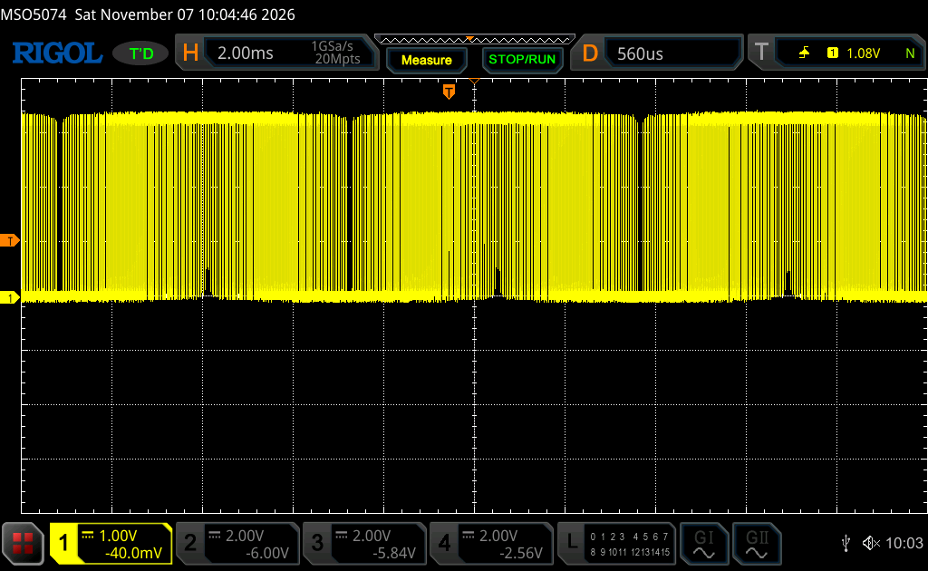
By probing PA5, using oscilloscope or logic, you should get something like this:
By applying a filter:
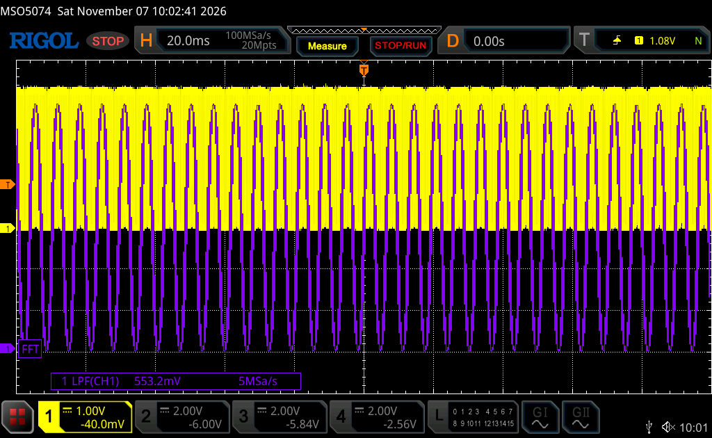
Note that we got beautiful sinewave using PWM and DMA.
Happy coding 😉
Discussion