In Part 1, we used a timer to measure time; now we’ll put it to work generating signals instead. In this part, we configure TIM2 in PWM mode using STM32CubeMX and produce a pulse-width modulated output — the technique behind LED dimming, motor speed control, servos, and countless other applications.
In this guide, we shall cover the following:
- Introduction.
- How to calculate the PWM frequency.
- STM32CubeMX configuration.
- Firmware development.
- Results.
1. Introduction:
In Part 1 of this series, we put TIM2 to work as a precision timekeeper — counting down milliseconds and telling the CPU exactly when to stop waiting. But timekeeping is only half of a hardware timer’s story. The same counting machinery that measured time can just as easily shape it, carving a repetitive clock signal into pulses of any width we choose. That technique is called Pulse Width Modulation (PWM), and it is arguably the single most used feature of any microcontroller timer. Once you understand it, you will start seeing it everywhere — in your phone’s screen backlight, in the fan spinning inside your laptop, and in the servo motor of every hobby robot ever built.
So what exactly is PWM? It is a square wave with a fixed frequency and a variable duty cycle — the fraction of each period during which the signal stays HIGH:
CCR = 25 %      ┌┐      ┌┐      ┌┐
                ││      ││      ││
              ──┘└──────┘└──────┘└──

CCR = 50 %      ┌──┐    ┌──┐    ┌──┐
                │  │    │  │    │  │
              ──┘  └────┘  └────┘  └─

CCR = 75 %      ┌────┐  ┌────┐  ┌────┐
                │    │  │    │  │    │
              ──┘    └──┘    └──┘    └─
The magic lies in what happens when this digital signal meets a physical system. A load powered by a PWM signal responds to its average value: with a 3.3 V supply and a 50% duty cycle, an LED behaves as if it were fed a steady ~1.65 V. Dim an LED to 25% and the pulses switch faster than your eye can perceive — it simply looks dimmer. Feed it to a motor and the winding inductance smooths the pulses into a lower average current, so it spins slower. The signal is purely digital (fully ON or fully OFF), yet the effect is analog.
And there is a deeper reason PWM is everywhere: efficiency. The analog alternative — dropping voltage across a resistor or a linear regulator — burns the excess energy as heat. A transistor driven by PWM, by contrast, is always in one of two ideal states: fully on (near-zero voltage drop) or fully off (zero current). Almost no power is wasted in the switch itself, which is why PWM rules everything from LED dimmers to electric vehicle inverters.
The applications are practically endless:
- LED dimming and display backlights — your phone’s screen brightness is PWM,
- DC motor speed control — via H-bridge drivers,
- Servo motors — a specific case: 50 Hz with 1–2 ms pulse widths encode the shaft angle,
- Switch-mode power supplies — buck and boost converters regulate their output voltage by adjusting duty cycle,
- Buzzers and crude audio synthesis,
- Heater and thermoelectric control — slow PWM keeps a temperature stable,
- Faking a DAC — filter PWM through an RC network to get an analog voltage.
Now, how does a timer actually generate this? This is the elegant part — and where the registers from Part 1 return with new roles. The counter (CNT) free-runs from 0 up to the auto-reload value (ARR), and this full ramp defines the period — hence the PWM frequency. Separately, the capture/compare register (CCR) holds a threshold. A dedicated hardware comparator watches the counter non-stop: while CNT < CCR the output pin is driven HIGH, and the moment the counter crosses the threshold, it snaps LOW (this is PWM Mode 1). The result: the duty cycle is simply CCR / (ARR + 1). Change CCR, and the pulse width changes on the very next cycle — handled entirely in silicon, with zero CPU involvement and zero jitter. Unlike Part 1, where the CPU sat trapped in a polling loop, here we configure the timer once and walk away; the pulses keep flowing while the CPU sleeps or does real work.
In this guide, we will configure TIM2 in PWM output mode using STM32CubeMX and the LL API, connect a channel to a physical pin, generate a signal at a chosen frequency, and vary the duty cycle at runtime — watching the result on an oscilloscope, or simply as a fading LED.
Along the way, you will learn:
- How CNT, ARR, and CCR work together to set both PWM frequency and duty cycle,
- How to configure a timer channel in PWM output mode in CubeMX,
- The minimal set of LL API calls to start PWM output,
- How to change the duty cycle on the fly — the foundation for fading LEDs, driving servos, and controlling motors,
- The resolution trade-off: why
ARR + 1defines how many distinct brightness/speed steps you get, and how resolution competes with frequency.
2. How to Calculate PWM Frequency:
PWM Frequency Equation
f_PWM = f_TIM_CLK / ((PSC + 1) × (ARR + 1))
where:
- f_PWM — PWM frequency (the update rate of the counter),
- f_TIM_CLK — timer input clock (e.g., 16 MHz on TIM2 with default HSI clock),
- PSC — prescaler value,
- ARR — auto-reload value.
Why it looks like this
The equation is just two division stages chained together:
f_CNT = f_TIM_CLK / (PSC + 1)        ← counter tick rate (Step 1: prescaler)
f_PWM = f_CNT      / (ARR + 1)       ← counter overflows every (ARR + 1) ticks (Step 2: period)
The +1 appears because both registers are zero-based: a prescaler value of 0 means “divide by 1,” and a counter counting 0 → ARR performs ARR + 1 steps per period.
Worked example (TIM2 @ 16 MHz)
| PSC | ARR | f_CNT | f_PWM |
|---|---|---|---|
| 16000−1 | 999 | 1 kHz | 1 Hz |
| 1600−1 | 99 | 10 kHz | 100 Hz |
| 160−1 | 99 | 100 kHz | 1 kHz |
| 16−1 | 99 | 1 MHz | 10 kHz |
| 1−1 | 15 | 16 MHz | 1 MHz |
For example, a 1 kHz PWM with 1000 duty-cycle steps (resolution):
f_TIM_CLK = 16 MHz,  f_PWM = 1 kHz,  resolution = 1000 steps

ARR + 1 = 1000  →  ARR = 999
PSC + 1 = 16 MHz / (1 kHz × 1000) = 16  →  PSC = 15
Handy rearrangements
Solve for ARR at a chosen frequency (keeping PSC fixed):
ARR = (f_TIM_CLK / ((PSC + 1) × f_PWM)) − 1
Solve for PSC (choosing ARR for your desired resolution):
PSC = (f_TIM_CLK / (f_PWM × (ARR + 1))) − 1
Bonus: duty cycle
Since your guide covers it, the companion equation is:
Duty cycle (%) = CCR / (ARR + 1) × 100
Together they give you the full design procedure: pick f_PWM → solve ARR (and PSC) → set CCR anywhere from 0 to ARR+1.
3. STM32CubeMX Configuration:
We shall continue from this.
Open the .ioc file of the project.
From Timers, select TIM2 and configure it as follows:
- Set Channel 1 to PWM Generation CH1.
- Set PSC to 0.
- Counter Period to 100.
- Mode to PWM Mode 1
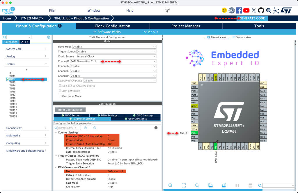
Note that PA0 is set to be TIM2_CH1 pin.
From the calculations, we can find that the PWM frequency will be 160KHz.
Finally, click on Generate Code. This will update the project files.
Thats all for STM32CubeMX configuration.
4. Firmware Development:
Open the project in STM32CubeIDE.
Open tim.h
In user code begin prototypes, declare the following functions:
void PWM_Start(TIM_TypeDef *TIMx, uint8_t channel);
This function will start the timer in PWM mode and it takes the following parameters:
- Instant to the timer to be used (TIM2 in this case).
- Channel to be enabled (Channel 1 in this case).
Next, declare the following function:
void PWM_SetDutyCycle(TIM_TypeDef *TIMx, uint8_t channel, float duty_cycle);
This function shall update the duty cycle of the PWM channel and it takes the following parameters:
- Instant to the timer to be used (TIM2 in this case).
- Channel to be enabled (Channel 1 in this case).
- Duty cycle value to be set.
Thats all for the header file.
Next, open tim.c source file
In user code begin 1:
We start by PWM start function:
void PWM_Start(TIM_TypeDef *TIMx, uint8_t channel)
Fist determine which channel to be enabled and enable it:
switch (channel)
    {
        case 1:
            LL_TIM_CC_EnableChannel(TIMx, LL_TIM_CHANNEL_CH1);
            break;
        case 2:
            LL_TIM_CC_EnableChannel(TIMx, LL_TIM_CHANNEL_CH2);
            break;
        case 3:
            LL_TIM_CC_EnableChannel(TIMx, LL_TIM_CHANNEL_CH3);
            break;
        case 4:
            LL_TIM_CC_EnableChannel(TIMx, LL_TIM_CHANNEL_CH4);
            break;
        default:
            return; // Invalid channel
    }
Next, enable the counter:
LL_TIM_EnableCounter(TIMx);
Finally, call update event to force load PSC, ARR and CCR as follows:
LL_TIM_GenerateEvent_UPDATE(TIMx);
Hence, the function as follows:
void PWM_Start(TIM_TypeDef *TIMx, uint8_t channel)
{
    /* Enable the capture/compare channel output */
    switch (channel)
    {
        case 1:
            LL_TIM_CC_EnableChannel(TIMx, LL_TIM_CHANNEL_CH1);
            break;
        case 2:
            LL_TIM_CC_EnableChannel(TIMx, LL_TIM_CHANNEL_CH2);
            break;
        case 3:
            LL_TIM_CC_EnableChannel(TIMx, LL_TIM_CHANNEL_CH3);
            break;
        case 4:
            LL_TIM_CC_EnableChannel(TIMx, LL_TIM_CHANNEL_CH4);
            break;
        default:
            return; // Invalid channel
    }

    /* Enable counter */
    LL_TIM_EnableCounter(TIMx);

    /* Force update generation to load PSC/ARR/CCR immediately */
    LL_TIM_GenerateEvent_UPDATE(TIMx);
}
Next, function to update the duty cycle:
void PWM_SetDutyCycle(TIM_TypeDef *TIMx, uint8_t channel, float duty_cycle)
First, clamp the duty values from 0 to 100:
    if (duty_cycle < 0.0f)   duty_cycle = 0.0f;
    if (duty_cycle > 100.0f) duty_cycle = 100.0f;
Next, determine the value to be updated from ARR value:
    uint32_t arr = LL_TIM_GetAutoReload(TIMx);
    uint32_t ccr = (uint32_t)((duty_cycle / 100.0f) * (float)(arr + 1));
Clamp the value:
if (ccr > (arr + 1)) ccr = arr + 1;
Next, update the CCR value:
switch (channel)
    {
        case 1:
            LL_TIM_OC_SetCompareCH1(TIMx, ccr);
            break;
        case 2:
            LL_TIM_OC_SetCompareCH2(TIMx, ccr);
            break;
        case 3:
            LL_TIM_OC_SetCompareCH3(TIMx, ccr);
            break;
        case 4:
            LL_TIM_OC_SetCompareCH4(TIMx, ccr);
            break;
        default:
            return; // Invalid channel
    }
Hence, the entire function:
void PWM_SetDutyCycle(TIM_TypeDef *TIMx, uint8_t channel, float duty_cycle)
{
    /* Clamp duty cycle to valid range */
    if (duty_cycle < 0.0f)   duty_cycle = 0.0f;
    if (duty_cycle > 100.0f) duty_cycle = 100.0f;

    /* Read current auto-reload value to compute compare value */
    uint32_t arr = LL_TIM_GetAutoReload(TIMx);
    uint32_t ccr = (uint32_t)((duty_cycle / 100.0f) * (float)(arr + 1));

    /* Clamp CCR to max ARR+1 (100% duty needs CCR > ARR) */
    if (ccr > (arr + 1)) ccr = arr + 1;

    /* Set the compare value on the requested channel */
    switch (channel)
    {
        case 1:
            LL_TIM_OC_SetCompareCH1(TIMx, ccr);
            break;
        case 2:
            LL_TIM_OC_SetCompareCH2(TIMx, ccr);
            break;
        case 3:
            LL_TIM_OC_SetCompareCH3(TIMx, ccr);
            break;
        case 4:
            LL_TIM_OC_SetCompareCH4(TIMx, ccr);
            break;
        default:
            return; // Invalid channel
    }
}
Next, open main.c.
In user code begin 2 in main function:
Start PWM for TIM2 channel 1 and set the duty cycle to 75% as follows:
  /* Start PWM on TIM2 Channel 1 */
  PWM_Start(TIM2, 1);
  /*Set duty cycle to 75%*/
  PWM_SetDutyCycle(TIM2, 1, 75.0f);
That’s all for the firmware development.
Thats all for the firmware.
Save, build and run the project on your board.

You may download the project from here.
5. Results:
By probing PA0 using oscilloscope or logic analyzer, you should we get the following:
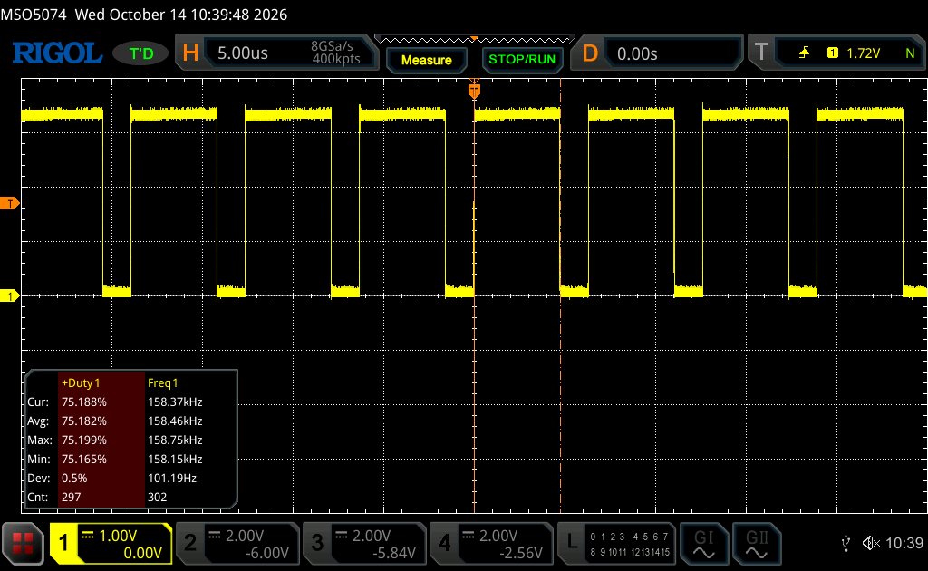
As you can see, we have almost 160KHz frequency and 75% for the duty cycle which is similar to our calculation earlier.
Stay tuned.
Happy coding 😉

Add Comment